2GIG TAKE-KIT1 Install Guide
Related Products

Related Categories
Document Transcript
Copyright © 2014 Linear LLC. 1
2GIG-TAKE-KIT1
HARDWIRE CONVERSION KIT
INSTALL INSTRUCTIONS
The 2GIG Hardwire Conversion Kit (2GIG‐TAKE‐KIT1) provides installers
with an easy method for taking over a pre‐wired security alarm system
and converting the existing hardwired zones to wireless zones.
To ensure optimal performance with the 2GIG Control Panel, the kit
provides an ABS Plastic enclosure (UL 94: V‐0) to protect the kit’s
components. The enclosure houses up to three (3) Super Switch
Takeover Modules (2GIG‐TAKE‐345) and the Power Supply Board with
backup battery charging circuit. It also includes a space for placing a
suitable backup battery.
The kit includes one (1) Super Switch Takeover Module (Wireless
Takeover of an Alarm System. US Patent No. 8,638,218). You can also
install two (2) additional modules, which permits you to convert up to 24
pre‐wired security zones to wireless zones (each module converts eight
(8) zones).
IMPORTANT: The Super Switch cannot be used to monitor Carbon
Monoxide (CO) or Fire detection zones and the Hardwire
Conversion Kit is intended for indoor use only.
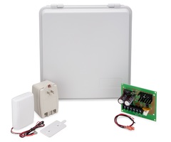
Figure 1 Hardwire Conversion Kit
Box Contents
Verify that the package includes:
• 1—Super Switch Takeover Module (2GIG‐TAKE‐345)
• 1—Plastic Bracket
• 2—Phillips Head Screws for Plastic Bracket
• 1—12/24 VDC Power Supply Board
• 1—16.5VAC 50 VA Grounded Plug‐in Transformer
• 1—ABS Plastic Wall‐Mount Enclosure
• 1—Removable Enclosure Door
• 4—Drywall Anchors and Phillips Head Screws for mounting
the enclosure.
• 1—Double‐sided Adhesive Tape for Super Switch Plastic
Bracket
• 3—2.5 inch (6.35 cm) Double‐Stick Foam Strips for Power
Supply Board
• 1—2.5 inch (6.35 cm) Double‐Stick Foam Strips for Plug‐in
Transformer
Additional Equipment
Additional equipment can be purchased to enhance the Hardwire
Conversion Kit:
• Backup Battery (Required). You must install a 12 V, 1.4 AH
Rechargeable Sealed Lead Acid Battery (or better).
• Linear H208 (Optional). This kit is recommended for locking the
plastic wall‐mount enclosure with a key for additional security.
For details, visit: http://www.linearcorp.com/
product_detail.php?productId=317
Mounting the Enclosure to the Wall
When completing the steps below, refer to Figure 2 "Mounting the
Enclosure to the Wall" on page 2.
To mount the enclosure to the wall:
1 Choose a location within RF range of the Control Panel. Before you
begin, ensure the mounting location is free of electrical wires and
plumbing systems before drilling into the wall.
2 Temporarily remove the enclosure door by lifting the cover up and
pushing it back until the door’s hinge pins disengage.
3 Using the four (4) keyhole slots as a template, mark the location of
the four (4) mounting holes at the top of the keyhole slots. Ensure
that the enclosure will be level.
4 Remove the enclosure from the wall and drill 3/16” starter holes for
the screws at the four (4) marked locations.
5 Push each of the wall anchors into the drilled holes, ensuring the
wall anchor heads are flush with the wall.
6 Screw two (2) of the Phillips head screws into the bottom wall
anchors, leaving the heads exposed.
Do not screw these in all the way.
7 Pull the cord for the Grounded Plug‐in Transformer through one of
the access holes or knockout in the back of the enclosure.
8 Pull the wires for all of the wired sensors through the enclosure’s
access holes and/or knockout as needed.
9 With the enclosure in place, insert the two (2) screw heads into the
top wall anchors.
Ensure the screw heads are at the upper end of the keyhole slots.
Then tighten both screws.
10 Lift the enclosure and insert the screw heads into the lower keyhole
slots.
11 Slide the enclosure downwards so the screw heads are at the upper
end of the keyhole slots.
12 Ensure that the enclosure is level.
13 Tighten the screws.
14 Continue with "Mounting the Power Supply Board in the Enclosure"
on page 2.
2 Copyright © 2014 Linear LLC.
Hardwire Conversion Kit (2GIG-TAKE-KIT1) | Installation Instructions
Figure 2 Mounting the Enclosure to the Wall
Mounting the Power Supply Board in the
Enclosure
To mount the power supply board inside the enclosure:
1 Attach the three (3) double‐stick foam strips (included) to the flat
surfaces on the back edges of the power supply board.
As shown in positions A and B in the figure below, do not affix the
foam strips over the edge with the exposed pins.
2 Affix the board to the lower‐right corner of the enclosure.
NOTE: For safety, ensure that the board is not covering the wiring
access or keyhole slots. See C in the figure below.
3 (Optional) Use four (4) sheet metal screws (not included) to secure
the power supply board to the enclosure.
NOTE: To avoid damaging the board, do not overtighten the
screws.
Figure 3 Mounting the Power Supply Board
Mounting the Super Switch in the Enclosure
To mount the Super Switch inside the enclosure:
1 Attach the adhesive backing to the back side of the plastic wall
bracket for the Super Switch.
The adhesive backing is included in the Hardwire Conversion Kit.
2 Affix the plastic wall bracket to the upper‐right corner of the
enclosure. See position 3 in Figure 4 Mounting the Super Switch in
the Enclosure.
NOTE: If installing more than one (1) Super Switch module,
mount each plastic wall bracket vertically as shown in Figure
4. The enclosure can house a maximum of three (3) modules.
3 Use the two (2) sheet metal screws (included with the Super
Switch) to secure the module to the inside the enclosure.
4 Slide the backplate of the Super Switch downwards over the
mounting stubs on the face of the plastic wall bracket.
5 To remove the Super Switch backplate from the plastic wall
bracket, slide the backplate in an upwards direction to release it
from the bracket’s mounting stubs.
Figure 4 Mounting the Super Switch in the Enclosure
Wiring the Components
Wiring must always be installed by qualified service personnel and in
accordance with National Electrical Code, as well as with all local
codes and authorities having jurisdiction.
NOTE: The Hardwire Conversion Kit is intended for indoor use
only.
To wire the components in the kit:
1 Connect the Ground and 12V wires from the Super Switch to the
+V and NEG terminals on the Power Supply Board.
NOTE: Refer to the wiring diagram in Figure 3 "Hardwire
Conversion Kit Wiring" on page 4.
2 Attach the positive (HI) side of each wire to the corresponding
zone on the super switch terminal block.
A One (1) Removable Cover
B Hinge Pins
C Four (4) Keyhole Slots
D Four (4) Plastic Wall Anchors (included)
E Four (4) Phillips Head Screws (included)
F Two (2) Access Holes
G One (1) Optional Knockout
A Three (3) Double‐Stick Foam Strips (Affix to Power Supply Board)
B Power Supply Board (Do not affix foam strips over exposed pins)
C Power Supply Board (Affix to back of enclosure)
A Super Switch Module(s)
B Plastic Wall Bracket(s) (brackets affixed vertically to back of enclosure)
C Double‐sided Adhesive Tape (included) and/or Optional Screws for Plastic Wall
Bracket
D Super Switch Backplate, Printed Circuit Board, and Wiring
E Super Switch Front Cover
Hardwire Conversion Kit (2GIG-TAKE-KIT1) | Installation Instructions
Copyright © 2014 Linear LLC. 3
NOTE: Terminals 3‐10 on the super switch correspond to zones 1‐
8. For example, wire the positive (HI) side of zone 1 on the
Super Switch to terminal 3.
3 Repeat the steps above for each additional zone.
4 Group the LO/(GND) wires together and connect them to terminal
1/G (GND) of the Super Switch.
5 Replace the front cover on the Super Switch.
6 Ensure the power supply is mounted in the enclosure included
with the 2GIG‐TAKE‐KIT1.
7 Position the backup battery in the recommended location in the
enclosure.
Figure 5 Recommended Location for Backup Battery (Not Included)
8 Connect the Super Switch to the backup battery as follows:
8a Connect the RED (BAT+) wire from the Super Switch to the RED
terminal on the backup battery.
8b Connect the BLACK (BAT ‐) wire from the Super Switch to the
BLACK terminal on the backup battery.
9 Connect the Power Supply wires to the backup battery as follows:
9a Connect the RED (BAT +) and BLACK (BAT ‐) wires (provided)
from the power supply to the BAT + and BAT ‐ terminals on the
Power Supply Board.
9b Connect the Spade Lugs to the Power Supply Ground and 12 V
wires to the corresponding Quick Disconnect Connectors on
the Super Switch wires. The Super Switch should already be
connected to the backup battery.
9c Connect the 16.5V AC leads for the transformer to the 16.5V
Power Supply.
NOTE: To avoid potential damage to the transformer and
connected devices, measure the transformer’s output voltage
before connecting it to the Power Supply Board.
IMPORTANT: To avoid nuisance low battery indicators from
connected zones, always power up the battery before
connecting AC power. If you experience an issue, see
Troubleshooting the Low Battery Alert.
10 Connect the 16.5 V AC leads to the AC terminals on the Power
Supply Board.
11 Connect the plug‐in transformer (included) into an unswitched
wall outlet.
12 Prepare to secure the transformer to the outlet as follows:
• For a standard wall outlet, screw the transformer to the outlet.
The screw is included with the plug‐in transformer.
OR
• For a decora wall outlet, affix the double‐sided adhesive tape
to the transformer. Then adhere the transformer to the outlet.
Figure 6 Connecting Power to the Hardwire Conversion Kit
Recommended Maximum Current Draw
The maximum current draw from external devices shall not exceed
the recommendations in the table below:
Troubleshooting the Low Battery Alert
If a low battery alert appears:
1 Unplug the transformer to power down the Power Supply.
2 Remove all connections from the battery.
3 Test the battery’s voltage with a battery life test meter (not
multimeter).
4 If the battery is fine, rewire the Super Switch.
5 After rewiring the Super Switch, reconnect the battery
connections, connect power to Terminal 2 on the Super Switch,
and then plug in the transformer.
NOTE: To clear the low battery alert, you may need to open and
close all of the zones or to reboot the Control Panel. To reboot
the panel, go to the Installer Toolbox, press System
Configuration, and the press End at the question screen.
When the Summary of System Configuration screen appears,
ensure the Save Changes box is selected. Then press Exit.
NOTE: All of the ground wires must be grouped together and
connected to the ground port of the Super Switch.
A Backup Battery
A Wall Outlet
B Plug‐in Transformer and Screw (included)
C Plug‐in Transformer and Double‐Sided Adhesive Tape (included) for Decora
Outlets
D Back‐side of Plug‐in Transformer with Double‐Sided Adhesive tape affixed
When this number of Super Switch
Modules are installed:
Do not exceed this maximum:
Three (3) Modules 350 mA
Two (2) Modules 400 mA
One (1) Module 450 mA
4 Copyright © 2014 Linear LLC.
Hardwire Conversion Kit Wiring
Use the diagram below when wiring the Hardwire Conversion Kit.
Figure 7 Hardwire Conversion Kit Wiring Diagram
Hardwire Conversion Kit (2GIG-TAKE-KIT1) | Installation Instructions
Copyright © 2014 Linear LLC. 5
Installing an Enclosure Door Lock
The removable cover on the plastic wall‐mount
enclosure is equipped with an knockout that
accepts the Model H208 Lock Kit from Linear
LLC. This lets you install an optional key lock.
To install the optional lock:
1 Temporarily remove the enclosure door.
2 Locate the knockout for the lock. This is
located in the center at the bottom of the
enclosure door.
3 Carefully remove the knockout from the
enclosure door using a punch tool.
4 Assemble the door lock as described in the H208 Owner’s Manual
(PN: 221963A).
Installing a Tamper Switch on the Enclosure
You can install an optional wired surface mount contact (not provided)
from a third‐party manufacturer to act as an alarm contact for
protecting the enclosure. If the enclosure’s cover is opened, the alarm
will be activated.
To install a tamper switch on the enclosure, use the following as a
guideline:
1 Follow the manufacturer’s instructions to mount the switch to the
inside surface of the wall‐mount enclosure.
2 Place the magnet on the removable door using double‐sided tape
or adhesive.
3 Route the HI side wire from the surface mount contact to any
available zone terminal on the Super Switch. Route the LO side to
the GND.
4 Replace the enclosure door. After connecting power to the kit, you
will need to program the tamper switch into the Control Panel. To
learn how to program sensors into the Control Panel, see the
Control Panel’s Installation and Programming Guide.
Figure 8 Replacing the Enclosure Door
SPECIFICATIONS
A Removable Enclosure Door (must be in “straight‐up” position to engage hinge
pins)
B Hinge Pins
Enclosure
Material and Certification ABS Plastic UL 94 V‐0
Dimensions 11.5 x 12.5 x 4 in (29.2 x 31.8 x 10.2 cm)
Takeover Module
Wireless Signal Range 350 ft, open air, with Wireless Control Panel
Code Outputs For each of the eight (8) serial zones: Alarm;
Restore; Fault; Low Battery
Transmitter Frequency 345.00 MHz (crystal controlled)
Unique ID Codes Over one (1) million different code
combinations
Supervisory Interval 70 minutes
Sensor Dimensions (LxWxH) 3.54 x 2.56 x 1.13 in. (9.0 x 6.5 x 2.9 cm)
Weight (including bracket) 2.85 oz. (80.8 g)
Housing Material ABS Plastic
Color White
Operating Temperature Limits 32° to 120° F (0° to 49° C)
Relative Humidity 5‐95% Non‐Condensing
Operating Voltage 9‐16 VDC, 50mA
Certification ETL, FCC Part 15, and Industry Canada
Power Supply Board
Input 16.5VAC, 20VA
Output 12/24 VDC
Battery Backup Built‐in charger for sealed lead or gel type
batteries, automatic switch over to stand‐by
when AC fails
Visual Indicators AC input and DC output LED indicators
Grounded Plug‐in Transformer
Primary 120VAC 60Hz
Secondary 16.5VAC 50VA
LED Indicator Supervises Power
Primary Termination 2 Male Blades and Grounding Pin
Secondary Termination 3 #6‐32 Screw Terminals with washers for
secure contact
Dimensions (W x D x H) 2.88 x 2.25 x 3.88 in (7.3 x 5.7 x 9.9 cm)
Weight 1.5 lbs
Color White
Surge Protection:
3 Mode Protection Line, Neutral, and Ground
Clamping Voltage 340V
Maximum Spike Current 4500 amps
Energy Dissipation 60 joules
Maximum Spike Voltage 6000Volts
Clamping Response Time 25 Nanoseconds
Certification UL & ULC Listed
6 Copyright © 2014 Linear LLC.
Hardwire Conversion Kit (2GIG-TAKE-KIT1) | Installation Instructions
Limited Warranty
This Linear LLC product is warranted against defects in material and
workmanship for one (1) year. This warranty extends only to
wholesale customers who buy direct from Linear LLC or through
Linear’s normal distribution channels. Linear LLC does not warrant this
product to consumers. Consumers should inquire from their selling
dealer as to the nature of the dealer’s warranty, if any.
There are no obligations or liabilities on the part of Linear LLC for
consequential damages arising out of or in connection with use or
performance of this product or other indirect damages with respect to
loss of property, revenue, or profit, or cost of removal, installation, or
reinstallation. All implied warranties for functionality, are valid only
until the warranty expires. This Linear LLC Warranty is in lieu of all
other warranties expressed or implied.
2GIG by Linear
1950 Camino Vida Roble, Suite 150
Carlsbad, CA 92008 USA
For technical support in the USA and Canada:
855‐2GIG‐TECH (855‐244‐4832)
Email: 2gigtechsupport@linearcorp.com
Visit web site for technical support hours of operation
For technical support outside of the USA and Canada:
Contact your regional distributor
Visit dealer.2gig.com for a list of distributors in your region
PN: 77‐000069‐001 Rev. B
- Uploaded