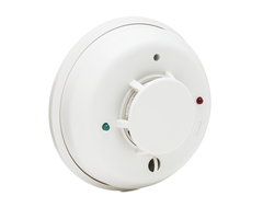
DSC PowerSeries Neo - COSMO2W/COSMOD2W Wiring and Programming
Related Products


Document Transcript
System Sensor
–
COSMOD2W
1
of
4
Ju
ly
20
24
NEO HS2016 / HS20
3
2
/ HS2064 / HS2128 v1.3
5+
The PowerSeries NEO supports
and is cross listed with t
he System Sensor
COSMOD
2W
which supports the
System Sensor
COSMO
-
2W
smoke
/co
detectors
.
The
COSMO
-
2W loop
is monitored by the NEO for three states of the
detector
’s
circuit
through the
fire zone
connection
to the COSMOD2W
(
SMK IDC +, SMK IDC
-
)
.
•
3.9
k resistance is
a
N
ormal
state
on the loop
.
5.6k
is
presented
to
the NEO.
•
Reduction of resistance toward 0k is
an A
larm
state
.
(Detector alarm or short)
•
Increase of resistance toward
∞ is a Trouble state.
(Loose or broken wire)
➢
Tech Tip
:
T
est each smoke
/co
detector for alarm
state
and the loop for
trouble
state.
Follow the
manufacturer’s
instructions
as needed
for testing.
➢
Tech Tip
:
Only use
compatible
de
tectors (COSMO
-
2W and/or 2WTA
-
B)
.
Do not
install other
devices on the alarm circuit (e.g., heat detectors, manual
pulls, etc.)
➢
Tech Tip:
Follow the manufacture
r
’s installation instructions for testing, power
calculations,
operation, and
installation requirements as needed.
Fire Fault
System Sensor
–
COSMOD2W
2
of
4
Ju
ly
20
24
Wiring:
5.6k Ohms
5.6k Ohms
1
EOL
Resistor =
3.9k Ohms
EOL Resistor = 3.9k Ohms
POWER IN
+
POWER IN
–
SMK
IDC +
SMK
IDC
–
CO IDC +
CO IDC
–
CO TRIGGER
BELL IN
EOL
SMK
EOL
SMK
EOL CO
K
EOL CO
K
ID
C
+
IDC
–
SMK TRIGGER
BELL IN
1
Use
5.6k Ohms
resistors for the EOL SMK and EOL CO termination.
System Sensor
–
COSMOD2W
3
of
4
Ju
ly
20
24
Panel Programming:
[ ] = NEO Panel Section
/ Solid ~ Red Lock light in programming /
{ } = NEO Subsection
/ Single Flashing ~ Red Lock light in programming /
( ) = Data
/
Solid ~ Green Check light in programming /
Section [001]
Zone Programming
{
005
2
} (008)
Program the zone as (008) Standard
24
-
Hour
Fire
{
006
2
} (041)
Program the zone as (041) 24
-
Hour CO
Section [
009
]
PGM
Definition Programming
{001
2
} (101)
Program PGM1 as (101) Burg and Fire
Bell
Follower
{002
2
}
(10
3
)
Program
PGM2 as (10
3
)
Sensor Reset
➢
Tech Tip:
PGM2 will provide up to 300mA when programmed as
(
103) Sensor Reset
.
Section [
010
]
PGM
Attributes
{001
2
}
Option 1
~ True Output = ‘N’
➢
Tech Tip:
The PGM
providing
the
fire
alarm trigger MUST be
inverted.
The panel will not reset properly if the PGM is not inverted.
Section [
013
]
Option 8 ~
Temporal Three Fire Signal
ing = ‘Y’
COS
MOD
2W
Setup:
The fire alarm output signal
from
PGM1 in this setup is coded as Temporal Three
Fire
Signaling
, the
COSMOD2W
D
ip
S
witch
#1
MUST be
set to ‘
ON
’.
2
Zone and PGM sections
are
based on
the
diagram on Page 2
–
adjusted as needed
.
System Sensor
–
COSMOD2W
4
of
4
Ju
ly
20
24
➢
Tech Tip:
When using the POS+ trigger following the
PGM
programmed
as
a (101) Burg and Fire Follower
,
any zone that
trips the
bell
output
will sound with it
s
cadence through the
smoke detecto
r
sounder
s
(
e.g., Fire Alarm
–
Temporal 3, CO Alarm
–
Temporal 4,
Flood
Alarm
–
1 second
pulse
,
Burg Alarm
–
Steady,
etc.)
The annunciation
patterns of the
sounders
will follow
the
priority
a
ssignment
of the alarm
condition
.
H
igher priority alarms will
override
the
annunciation
of
the
lower p
riority alarms as
needed:
Fire, CO,
then
all
other
.
➢
Tech Tip:
When using
a
POS+ trigger
that
follow
s
the
(101) Burg and
Fire
Follower PGM output,
the CO Trigger
wiring
is optional.
The COSMOD will automatically
follow the bell
trigger
from
the SMK Trigger
as mentioned above.
➢
Tech Tip:
When a detector is removed from its base, or the
IDC detector
loop
is
disconnected/interrupted from the CO
SM
OD a Wire Fault
trouble
(Wire Fault
LED
=
solid) will occur on the
COSMO
D, this will cause
a
Fire
Trouble on the
assigned
fire zone
.
Once the detector loop is
properly restored, the COSMOD’s Wire Fault trouble should clear in
approximately 60 seconds, at which point clearing the NEO trouble.
Or once the detector loop is properly restored, t
he
COSMOD’s
Wire
Fault
condition can
be
immediately
clear
ed
by resetting the
module
by entering
[*][7][2]
or by
pressing the RESET
function key on
the
keypad for
two
seconds.
➢
Tech Tip:
When using the
COSMOD with the
COSMO
-
2W
devices and
connecting the
CO IDC
output
of the module into a zone of
the NEO panel for CO monitoring,
the COSMOD
will
trigger
a
momentary
zone fault
trouble
on the assigned CO zone of
the NEO
when the fire alarm
is reset
(e.g., [*][7][2] or RESET
.)
With
the proper setup
and wiring
of the COSMOD
,
there
is
no
way
to avoid th
e
momentary
zone fault on the
assigned
zone.
The
panel do
es
not
momentary
shunt the
loss of power
condition
for
the
CO zone
s like
it does
for
the fire
zones
.
This is normal.
- Uploaded


