Honeywell 6280 Installation Manual and Setup Guide
Related Products
Related Categories
Document Transcript
6280 TouchCenter Keypads Installation Guide
For Online Support visit: http://www.security.honeywell.com/hsc/resources/MyWebTech/
Ê800-07600ÀpŠ
800-07600 7/11 Rev. A
General Information
This guide provides information on installing and setting up Honeywell's 6280 TouchCenter Keypads. The 6280 Series graphical touch-screen keypads are Advanced User Interface (AUI) devices, which combine control of your security system, multi-media and premises lighting. Compatibility: For a list of alarm systems that the TouchCenter can interface with, refer to the Compatibility Table in this document. Wiring IMPORTANT: If you power the TouchCenter from your panel’s auxiliary power output, check your panel’s Installation and Setup Guide and verify that this device and others do not exceed your panel’s auxiliary power output capability; if it does, a supplementary power supply is needed. Word List The 6280 TouchCenter can annunciate a series of words. You must use the vocabulary list in your alarm panel instructions for actual words that may be annunciated; refer to the Word List in this document.
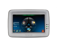
6280 TouchCenter
Front Panel LEDs
SD/SDHC CARD Slot
ARMED (RED) LED ON – System is armed. OFF – System is not armed. READY (GREEN) LED ON – System is disarmed and ready to arm. OFF – System is armed or disarmed but not ready. If disarmed, faults or troubles are present. MESSAGE (YELLOW) LED FLASHING – The system contains new message(s) for the User. OFF – No new messages.
RESET BUTTON Press to unlock keypad
6280-001-V0
Mounting the TouchCenter
This Keypad is for indoor use only and should be mounted at a comfortable viewing level. Avoid mounting in areas of high condensation such as bathrooms or in locations where bright light or sunlight shines directly on the screen. The TouchCenter can be mounted with or without the mounting plate. Use the center securing screw for European installation. Standard Mounting with mounting plate: Mounting without mounting plate:
1. Select a mounting location. 2. Detach the mounting plate by sliding downward. 3. Use the mounting plate to mark the location of the mounting holes on the mounting surface and check for level. 4. Locate the mounting plate over the mounting surface such that the wire/cable access openings are aligned while passing the wires/cable through the case back. ***Go to “Wiring the TouchCenter” and complete wiring*** 5. Secure the mounting plate to mounting surface using 4 screws (supplied). 6. Slide TouchCenter onto mounting plate.
MOUNTING SCREWS (4) (TYP) WALL SURFACE
The 6280 complies with the European Standard EN50131 and is designed to prevent unauthorized use.
Mounting (European Installations) using a center securing screw:
1. Detach case front by removing the two bottom screws. Gently pull up using a screwdriver if necessary and pry apart. Lift off cover. 2. Mount the TouchCenter in its final location, (see “Standard Mounting” or “Mounting without the mounting plate”) install center securing screw (supplied) and tighten to mounting surface. 3. Replace the case front and secure using the two bottom screws.
1. Select a mounting location. 2. Detach the mounting plate by sliding downward and discard. 3. Use the template (provided in the carton) to mark the location of the mounting screws and the cut-out for the TouchCenter assembly on the mounting location. Check for level. 4. Install 4 screws (supplied) in the mounting surface leaving screw heads 1/8” above the mounting surface. 5. Locate the case back over the mounting surface such that the opening is aligned with the wire/cable access opening on the mounting surface while passing the wires/cable through the opening in the case back. **Go to “Wiring the TouchCenter” and complete wiring 6. Mount TouchCenter by sliding onto the screw heads.
WALL SURFACE
CASE FRONT
INSTALL TAMPER SCREW
6280
SE
RIE
SC
AS
EB AC K
43/4 "
TEMPLATE
MO UN TIN GT EM PL AT E
CASE BACK
CU
T-O
UT
LO
CA TIO
N
DETACH CASE FRONT BY REMOVING SCREWS (2) AND LIFT UP
6280-015-V0
DR
ILL
LE
6280-006-V0
Wiring the TouchCenter
Mechanical Specifications:
Width: 8 inches (203.2mm) Height: 5-1/2 inches (139.7mm) Depth:1-3/8 inches (35mm)
CONTROL TERMINAL STRIP POWER FROM SUPPLEMENTARY POWER SUPPLY IF USED SUPPLEMENTARY +12 VDC POWER SUPPLY P/N AD12612 CONTROL TERMINAL STRIP AUX AUX DATA DATA IN OUT
6280-016-V0
WALL MOUNTING PLATE (OPTIONAL)
3/1 6" 4 PL DIA AC . HO ES LE
S
800-
DIA
. HO
3 - 9/16"
Ê8 00 0883 -0 08 1 5/11 31 Rev uŠ .A
DR
ILL
3/1
6"
MOUNTING SCREWS INSTALLED 1/8” ABOVE SURFACE
Electrical Specifications:
Backlight OFF, Sound OFF Backlight ON, Sound OFF Backlight ON, Sound ON 12V, 140mA 12V, 205mA 12V, 270mA 93% RH, no condensation 14˚ F to 131˚ F / -10˚ C to 55˚ C -40˚ F to 158˚ F / -40˚C to 70˚C
6280
YELLOW (DATA FROM CONTROL)
Y
AUX AUX DATA DATA IN OUT
RED (+12VDC) BLACK (GND)
Operating Environment:
Humidity
G
Temperature:
Operating Shipping / Storage
GREEN (DATA TO CONTROL)
BLACK RED GREEN YELLOW
BLACK
Wire Gauge:
#22 gauge #20 gauge #18 gauge #16 gauge
Length
150 feet 240 feet 350 feet 550 feet
6280-014-V0
UL
Use a UL Listed, battery-backed supply for UL installations. The battery supplies power to these keypads in case of AC power loss. The battery-backed power supply should have enough power to supply the keypads with the UL required minimum standby power time. IMPORTANT: Keypads powered from supplies that do not have a backup battery do not function if AC power is lost. Make sure to power at least one keypad in each partition from the control’s auxiliary power output or UL Listed battery backed up power supply.
IMPORTANT: When the TouchCenter is powered from an auxiliary power supply, always apply power to the control panel first and then the TouchCenter. Failure to observe this sequence results in improper operation of the TouchCenter and may result in an ECP Error indication. Connect the wires to the TouchCenter terminal block as shown.
• Connect the TouchCenter in parallel with keypads and other peripheral devices using the keypad data (ECP) bus. • If the TouchCenter is used as the primary system keypad, maximum wire run length is 150 feet. • If more than one keypad is wired to one run, then the maximum lengths must be divided by the number of keypads on the run. (e.g., the maximum length is 75 feet if two keypads are wired on a #22 gauge run). Note: Unshielded 4-conductor cable is recommended for the power/data wire.
Initial Setup
Programming the Control Panel The TouchCenter is not fully operational unless its address in the control panel has been enabled (set as an alpha console) AUI type device, and assigned to a partition (where applicable). We recommend that you use either a standard alpha keypad or the TouchCenter in Console Emulation Mode when programming the control panel. When in the Console Mode, the TouchCenter emulates an alpha keypad and the programming of the panel is performed following the procedures provided in your panel’s Installation & Setup Guide. Note: When programming your control panel, if you change the zone types for your emergency zones you may disable the emergency icons in the TouchCenter. The emergency icons in the TouchCenter are active for zone types 06 and 07 (Panic icon), 08 (Medical icon), and 09 (Fire icon). Additionally, the Medical icon is also compatible with a zone type 15 (24-Hour Medical) for panels that contain this zone type. The TouchCenter should not be assigned as a Master Console. If the TouchCenter is assigned as a Master Console, partitions must be controlled from the Partition screen or by using the Console Emulation Mode. TouchCenter Initialization When initially powered, the screen displays the boot sequence and the "Set ECP Address" screen is displayed. If the system is incorporating only one TouchCenter, leave the address set to 1 and touch Apply. The boot-up process continues until completion. If there are to be additional TouchCenter units in the system, after enabling addresses in the control panel using an alpha-keypad, power-up each TouchCenter one at a time, and set its address to one of the addresses you enabled in the control panel. Note: If the top of the screen is displaying ECP Error, the TouchCenter ECP Address is not valid for the panel that it is connected to. To change the ECP Address, enter the default code of “4140” to advance to the next screen. Note: 4140 is the TouchCenter default installer code before connecting to a control panel. Once connected to a control panel, use the panel’s installer code. Change the ECP Address on the unit, using the Up/Down arrows and then touch apply to accept the address and reset the TouchCenter. Once communication has been restored, then use the standard panel installer code for all installer functions. Refer to “ECP Setup” section. Time/Date Setup If not already set from the panel, set the current time and date. Refer to “Time/Date Setup” section. NIGHT Setup The TouchCenter is defaulted to arm the system in the STAY INSTANT mode when arming the system using the NIGHT icon. Select the arming mode to be activated when the NIGHT icon is touched on the "Arming" screen, refer to “Night Setup” section. * Refer to the instructions on the following pages to customize your TouchCenter.
HOME
Ready To Arm
SETUP
Ready To Arm
DISPLAY & AUDIO
Ready To Arm
SYSTEM SETUP
Ready To Arm
CS Setup
MULTI-MEDIA
Ready To Arm
Backlight Off After 5 Min
To Homepage After 30 sec
Auto Slideshow After 5 Min
Wed
01/19/2000
Security Light
System Info System Setup
16:07HRS
Operating Modes Chime Mode Voice Mode Voice Chime
Time/Date Setup User Setup
Video
Message
MultiMedia
P1 H
Disp & Audio Setup 0 8 : 5 7 P M Tu e 0 1 / 11 / 2 0 0 0
CLEAN SCREEN
P1 H
Advanced Setup 0 1 : 0 0 A M We d 0 1 / 0 1 / 2 0 0 3
Picture
Adjust the Brightness / Volume
1. Touch the Setup icon located in the lower left corner of the “Home” screen. 2. Move the Brightness/Volume slide bar to adjust the brightness/volume. From the “Setup” screen; 1. Touch the Disp&Audio Setup icon. 2. Enter your “Authorized Code" if required. 3. Select Chime Mode or Voice Mode to turn the mode on or off.
Notes
If changes are made, when you exit a Settings Changed! Pop-up window is displayed asking “Remember New Settings?“ Yes saves the change. No discards the change.
Navigation Icons
ICON ICON TITLE
“Intro Video”
FUNCTION
Accesses the Product Introduction Video. Record and retrieve Voice Messages. Turn certain devices on and off (if installed and programmed by your installer.)
Chime Mode, Voice Mode, Voice Chime
Notes
If the Chime Mode and Voice Mode are both selected, the Voice Chime is automatically selected. It may take a few seconds for the Chime Mode to take effect. When the TouchCenter exits the “Operating Modes” screen, your selection is saved. "Security” “Message”
"Light”
Accesses "Security" screen.
Adjust the Screen Timeouts
1. Touch the Disp&Audio Setup icon. 2. Enter your “Authorized Code" if required. 3. Touch the desired selection from the dropdown list displaying the time period for each option.
Yes saves the change. No discards the change.
Notes
If changes are made, when you exit a Settings Changed! pop-up window is displayed asking “Remember New Settings?“ Settings include: • Backlight Off After X time • Return To Homepage After X time • Auto Slideshow After X time. “Home” Returns you to the "Home" screen.
From the “Setup” screen;
“Back”
Reverts to the last screen viewed. Displays Emergency functions (as programmed by the installer). See Programming the Control Panel note. Note: This icon is displayed and active on all screens except while in the Clean Screen mode and during an LCD Display test in Diagnostics. This icon alerts the user to a Control Panel Message. Accesses the Message, Picture and Video feature.
Clean Screen
2. Touch the Disp&Audio Setup icon. 3. Enter your “Authorized Code" if required. 4. Touch the CLEAN SCREEN icon to disable the TouchCenter for 30 seconds so you can wipe the screen clean. A pop-up window displays "Touch Screen has
been disabled so that you may wipe the screen clean. Please use a damp, soft cloth. DO NOT use any liquids, sprays, or ammonia-based cleaners. Press CONTINUE to disable touchscreen." ** Panics cannot be initiated during this process**
Notes
At the "Touch Screen Disabled for =30 Seconds" screen, the touch screen should be wiped clean of fingerprints using a mild soap solution and a soft cloth. When the counter reaches zero, the window automatically closes and the touch screen is active. IMPORTANT: Do not use an abrasive cleaning agent or abrasive cloth when cleaning the TouchCenter or damage to the touch screen may occur. NOTE: The Emergency screen cannot be accessed while running in the clean screen mode. Touch Cancel to exit.
1. From the “Home” screen, touch the Setup icon.
“Panic”
“Control Panel Message”
“Multi-Media”
“Setup”
Allows access to Setup menus.
Multi-Media: Video Setup
1. Insert your personal media (SD/SDHC) card first. 2. Touch the Multi-Media icon, and then touch the Video icon. 3. Highlight a video file from the list and touch Play to start the selected video file. • Use the slide bar to scroll through the video list. • If desired, touch the Full View icon to view video in full screen.
Notes
NOTE: The VLC Video Converter is required to convert videos for proper playback on the 6280. Use an Internet search engine to locate and download the VLC Player/Converter, then follow the steps in the “VLC Video Converter Instructions” guide (provided in the carton). NOTE: Maximum video resolution should not exceed 400 x 240. Video files can be viewed from an (SD/SDHC) Card. Users can touch the appropriate icon to Play, Pause, view a Full View or Repeat the video. NOTE: If the video file causes the keypad to lock, press the reset button on the bottom of the keypad to reset the keypad. “Voice Status” Allows user to hear system status.
“Video”
Allows user to play video files.
“Picture”
Allows user to display personal photos in a slide show format. Minimizes the Home screen icons when viewing wallpaper displays. Maximizes the Home screen icons when viewing wallpaper displays.
“Minimize Home” “Maximize Home”
Video Icons
Play Pause Full View Repeat
Panel Default Displays
The “Security” screen displays an Icon(s) if a panel fault occurs. The following lists the Icons that are displayed to the left of the Panic icon.
Picture Setup
1. Insert your personal media (SD/SDHC) card first. 2. Touch the Multi-Media icon, and then touch the Picture icon. 3. Select the type of viewing transition desired by touching the Transition arrow. Select from (Standard, Horizontal, Vertical or Fade Out). 4. Touch the Slide Delay arrow to select the time interval (5, 10, 15, or 20 seconds) that you want to allow for each photo being viewed. To set a picture as wallpaper: 1. Use the slide bar to scroll through the list of pictures and highlight the file you want to be displayed on the keypad screen. 2. Touch the Set Wallpaper icon; view your selection from the “Home” screen.
NOTE: When viewing wallpaper displays, the Home screen icons can be minimized by touching the “Minimize Home” icon. Touch the “Maximize Home” icon to maximize Home screen icons.
Notes
The Picture feature allows you to set up and view photos as a slide show or as your wallpaper display. Photo files can be viewed from the (SD/SDHC) Card. Formats supported are .bmp or .jpg files. NOTE: • To exit the Picture feature at any time and resume keypad operation, touch anywhere on the screen. • The first image is displayed and a list of stored images appears on the screen. • When an image is loading, no other Picture Setup functions can be performed (play, previous, next, add or set wallpaper). Touch the TOP button to move up one level in the directory. Touch the OPEN button to view larger images and/or open directories, select from the list of stored images. Touch the CLEAR ALL button to clear all pictures from the current slide show rotation. Touch the Picture icon (on the Home screen) to go into the Slide Show feature.
ICON
MEANING
AC Loss; The system is not receiving AC power. Bell Failure; The system bell or siren has a problem. Note: This Icon is displayed when interfacing with residential panels only. Expander Failure; The system has a failure in an expansion module. Low Battery; The system battery, that powers the system during an AC power loss, is low. LRR Supervision Failure; The Communication Device used to communicate with the central station has a supervision failure. Max Attempts Exceeded; The system has exceeded the maximum attempts to communicate with the Central Station. Pager Failure; The system cannot communicate with an assigned pager. Telco-1 Cut; The system is not able to communicate with the central monitoring station over the primary phone line. Telco-2 Cut; The system is not able to communicate with the central monitoring station over the secondary phone line. Wireless Failure; The system is not able to communicate with its wireless devices.
Picture Icons
Play Image
Previous Image
Next Image
Add Image
Minimize Home
Maximize Home
-2-
CS Setup
1. From the System Setup screen, touch the CS Setup icon. 2. Enter your “Authorized Code", if required. 3. Touch the ECP Address icon.
Notes
When the TouchCenter cannot communicate with the alarm panel, the message “ECP Error” is displayed, check the following: •Verify that the AUI type device is enabled in the control panel, and that the ECP address in the TouchCenter matches the address enabled in the control panel. Use a different address for each device. • If powering the TouchCenter from a power supply, make sure you have a common ground installed (wiring between Power Supply "gnd" and panel "Aux. power neg"). On residential control panels (VISTA-20P or equivalent), up to four TouchCenters may be used. Addresses 1 and 2 (in field *189) are enabled by default. If the defaults have been changed, enable these addresses (in field *189) using an alphakeypad and the Data Field Programming procedures located in the panel Installation and Setup Guide. On commercial control panels (VISTA128BP, VISTA-128FBP or equivalent), These addresses in the control panel are normally not defaulted for AUI type devices. To enable the addresses you are using for TouchCenters, use an alpha-keypad and follow the procedures for “Device Programming” in your control panel “Programming Guide.”
COMPATIBILITY TABLE
Alarm System VISTA-15P VISTA-20P VISTA-20P VISTA-21IP VISTA-128BP VISTA-128FBP VISTA-128FBP-9 VISTA-250FBP-9 VISTA-250BP VISTA-250FBP VISTA-250FBP VISTA-128BPE VISTA-250BPE VISTA-128BPEN VISTA-128BPLT VISTA-128FBPN VISTA-128BPT VISTA-250BPT VISTA-128BPTSIA FA148CP FA168CPS FA1660C FA1660CT FA1670C-9 FA1700C Maximum Number of TouchCenters Minimum Software Revision Level
ECP Address
1 2 3
1. Touch the ECP Address icon. 2. Select the ECP address for this TouchCenter using the Up/Dn arrows. 3. The available ECP addresses are: 1-2, 5-6 for residential controls 1-2, 3-30 for commercial controls under Rev. 10 supports 3 AUIs. See Important Note below. 1-30 for commercial controls Rev. 10 and higher supports 6 AUIs.
IMPORTANT: If multiple TouchCenters are being used, they must be set to addresses 1, 2, and X (where X equals any address from 3 through 30). Only one AUI type device may be assigned to an address from 3 through 30 on commercial control panels. The TouchCenter should not be assigned as a Master Console. If the TouchCenter is assigned as a Master Console, partitions must be controlled from the Partition screen or using the Console Emulation Mode.
NOTE: When the ECP address is changed, and Apply is selected, the TouchCenter resets.
2 2 4 4 3 3 3 3 3 1 3 3 3 3 3 3 6 6 6 2 4 3 6 3 3
3.0 3.0 5.0 1.0 3.2 1.6 4.1 4.1 2.4 1.5 2.0 4.4 4.4 7.0 6.0 5.1 10 10 10 3.0 5.0 3 10.1 4.1 3
Apply accepts the address setting.
Lighting/EN50131 Display
1. From the System Setup screen, touch the CS Setup icon. 2. Enter your “Authorized Code", if required. 3. Touch the Options icon. 4. Select "Lighting" or "EN50131 Display" to turn the option on or off. 5. Select "Normal Mode" or "Safe Mode" to turn the option on or off. Apply accepts all changes.
Notes
The EN50131 Display compliance feature is a European Standard designed to prevent unauthorized users from knowing the status of the Security System. Note: DO NOT select the Demo Mode option. This option should only be selected if instructed to do so by factory service. When this option is selected, the keypad does not communicate with the control panel and any user can select Advanced Setup screens.
When the EN50131 Display feature is turned ON: •The keypad returns to the "Home" screen after 30 seconds and the "Armed" and "Ready" LEDs turn OFF. •The "To Homepage After" time setting changes to 30 seconds and the time is non-selectable. •The Security, Message and Lighting screen does not display system status until an authorized user code is entered. • The "Setup" menu does not display system status until an authorized user code is entered. Operating Modes Automatic Entry- In the rare event that the TouchCenter cannot successfully communicate in its graphic mode with the control panel, the TouchCenter displays “Problems detected. Start Keypad in Safe Mode?” and requests a “Yes” or “No” response. If you answer with “Yes”, the TouchCenter enters into the Safe Mode. If you answer with “No”, the TouchCenter tries to communicate with the panel again. After 3 consecutive times of receiving no response, the TouchCenter enters the Safe Mode automatically. Manual Entry - Note: ONLY enter the Safe Mode from the Normal Mode. Entering the Safe Mode from the Demo Mode may result in incorrect display of the Emergency Function keys.
Safe Mode
! SAFE MODE !
Notes
The Safe Mode may be automatically entered by the TouchCenter program on a communication failure or may be entered manually on command. While in the Safe Mode, the Home screen displays the Security, Panic, and Message Icon. A message !SAFE MODE! is be displayed at the bottom of the screen.
1. Select Safe Mode and then touch Apply. 2. Touch the OK icon. 3. To exit, touch the safe mode bar and touch Yes to return to Normal Mode. The TouchCenter resets and restarts in the Safe Mode.
Screen Security
1. From the System Setup screen, touch the CS Setup icon. 2. Enter your “Authorized Code", if required. 3. Touch the Screen Security icon. 4. If authority levels are correct, touch Back or Home to exit menu. 5. If changes are necessary, select the line to be changed and the level of user to have access, then select the OK icon.
Notes
Note: The Screen Security screen contains a heading of Advanced Setup, Central Station Setup, Disp. & Audio Setup, Event Logs, Lighting, Message, Security, and Time/Date. The Screen Security screen is redisplayed listing any changes. Note: The User Levels listed on this screen match the User Levels in commercial panels. See the chart below for corresponding User Levels in Residential Panels.
Code Authority
1. Touch the Code Authority icon. 2. Enter the 4-digit User Code for the user that you want to obtain Authority Level information about. 3. Touch the BACK icon.
Notes
The Code Authority icon displays User Names and Partition Authority Level for the User Code.
Operating in the Safe Mode This is a limited mode of operation. While in this mode: • You can use the Security icon to access the Console Emulation Mode of operation to try to clear your faults, disarm the system, or enter additional Alpha Keypad commands specified in your panel User and Installation Guides. You can perform almost all functions that you can perform from a standard non-graphic alpha keypad. • You can touch the “Panic” icon and generate Emergency Messages as defined in the panel's home partition for this TouchCenter. • The Armed and Ready LEDs on the front of the TouchCenter indicate the TouchCenter’s home partition status. • The Chime mode functions in the Safe Mode: however, there is no Voice, Voice Chime, or Message capability. WARNING: The Slide Show feature does not start automatically in Safe Mode.
User Code Setup Each user must be assigned a name with a corresponding 4-digit user code in order to gain access to various features and functions. The TouchCenter can hold the identity for 10 Users in its memory. If additional Users are needed, define the additional Users using the Console Emulation Mode. Users for the system are programmed in a central user setup location that provides the specific questions for authorization levels assigned to different users. You may want these users to be the same, but there are situations in which you may want a user to have limited capabilities. User Related Note • Users added to the system using the TouchCenter graphic user screen must be deleted from the TouchCenter using the graphic screen as well. Deleting users from the panel by any other means (alpha keypad, console emulation mode, or Compass downloader) does not automatically delete them from the TouchCenter. • If the panel has exit tones enabled and you arm the system in the Away mode, the TouchCenter beeps continuously throughout the exit period. • Use the console emulation mode for the following functions: - Programming more than 10 system users. - Programming the Pager report option for users of residential control panels (e.g., VISTA-15P and VISTA-20P). - Special Function Key operations (macros or single-button paging). - End-User Scheduling. - To check for an “Alarm Cancelled” message if this feature has been enabled in the system.
Device Events
1. Touch the Device Events icon. 2. To view a record of events in a history log, touch the up/down arrow to scroll.
Notes
The control panel must be programmed to record various system events in installer programming mode.
Panel Configuration
1. Touch the Panel Config icon. If you select OK, the TouchCenter resets and the panel configuration is downloaded from the panel into the TouchCenter.
Notes
A "Panel Configuration" screen is displayed providing details of your system. Delete clears the configuration from the TouchCenter and reloads the panel configuration into the TouchCenter.
Add/Delete/Edit a User
1. From the System Setup screen, touch the User Setup icon. 2. Touch the ADD User icon and enter your “Authorized Code”. 3. Touch the box next to Enter User Name; enter user name. 4. Touch the OK icon. 5. Touch the box next to User Number; enter User Number for this user. 6. Touch the box next to Enter User Code; enter the User Code for this user. 7. Touch the box next to RF Button Zone; enter the 3-digit RF Button Zone for this user. 8. Touch Save. Follow this procedure for deleting and editing users.
Notes
Note: The authorized code for adding, deleting and editing users is dependent upon the alarm panel you are connected to. Check your alarm panel Installation and Setup Guide to determine who can add users. Type in the user name (6 characters max.; no spaces between characters) Notes: • Use the Shift key for capital letters. • Use the BS (Backspace) key to make corrections. The @#$ key is not available for use at this time. If assigning this user to a wireless key, enter one of the zone numbers of the keyfob (the wireless key must be programmed before it can be assigned to a user). NOTE: To edit a User ‘name’ or ‘number’, you must delete the User and re-enter.
-3-
Time/Date Setup
1. Touch the Time/Date Setup icon; enter your “Authorized Code”, if applicable. 2. Touch the DST icon to have daylight savings time affect your system clock. 3. Set the “Start DST” and then the “End DST” settings by touching the Month, Weekend and Time (1 AM or 2 AM) "arrow" icons. 4. APPLY saves the settings. 5. Set the current time by following the prompts and select the current Month, Year, Hour, Minute, AM or PM and Month/Day/Year format. 6. Touch Apply.
Notes
If DST On (Daylight Savings Time) is selected, the TouchCenter adjusts for Daylight Savings time at the month, week and time chosen. Make sure "DST On” is checked to enable this feature. Select YES on the ”Time Setting Confirmation” pop-up window to save the changes in your security system. Select No to have the changes affect the TouchCenter only. Note: A Yes response is recommended. You can set the time and date from the Set Time & Date screen. • When the time is set it is stored in the TouchCenter and sent to the control panel when you touch the Apply icon and answer Yes to the following prompt. Additionally, when using the TouchCenter with a residential panel, the panel downloads its time into the TouchCenter once an hour after the clock is set. • If Get Time is touched, the TouchCenter downloads the time and date from the control panel and exits the Set Time & Date screen. Note: This icon appears with residential panels only (e.g., VISTA15P, VISTA-20P).
Diagnostic Tests
1. From the System Setup screen, touch the Advanced Setup icon. 2. Enter your “Authorized Code”. 3. Touch the Keypad Reset icon. 4. Touch the Keypad Test icon. 5. Touch the Test icon associated with the LCD Display Test. Follow the prompts to complete this test. 6. Touch the Test icon associated with the Audio Test; "Testing..." is displayed while beeps sound from the speaker. 7. Touch the Test icon associated with the LED Test; "Testing..." is displayed while the 3 LEDs light sequentially, top to bottom (red, green, yellow) 5 times.
Notes
If the keypad requires resetting, touch OK and the keypad resets. If Cancel is selected, keypad does not reset. Keypad Test A series of diagnostic tests are provided that allow verification of correct operation of the TouchCenter and its connections to the security system. There are a total of three diagnostic tests: LCD Display Test, Audio Test and LED Test. Performing Diagnostic Tests Select any diagnostic test from the Diagnostics screen by touching its associated Test icon. All or any individual test may be run when you access the Diagnostics screen; however, each test must be performed one at a time. At any time when a test is not being performed, you can touch the back icon to return to the previous screen, or touch the home icon to return to your home page. Residential System Notes • If the Clean Me option is set, when the maintenance signal is received a “Fire Maintenance” message and the Display Faults icon is shown. However, if you display the faults, zone 1 is not shown as a faulted zone. • If RF Jam Reports are selected and RF Jam is detected, the User Authorization screen displays “Trouble ZN100 RF Receiver”. If you enter the console emulation mode, the display shows “Check 90 RF Receiver Jam”. • Do not use the Custom Word reminder feature. NIGHT Setup Icon Function The TouchCenter is defaulted to arm the system in STAY INSTANT mode when arming the system using the NIGHT icon. You can change the TouchCenter so that it arms the system in a different mode when the NIGHT icon is touched by selecting the arming mode to be activated when the NIGHT icon is touched on the “Arming” screen. Note that some displays on the TouchCenter may not have enough space to display the whole name of a partition. When this occurs, the display shows as many characters as possible starting at the beginning of the partition name. We recommend that the partition name be kept to a maximum of 7 characters to ensure the “H” which indicates the home partition may be seen (this is set at the panel).
After each type of display, you are asked if the display was proper. If you touch the Yes icon, "Passed" is displayed in the test status column on the "Diagnostics" screen. If you touch the No icon, "Failed" is displayed in the test status column on the "Diagnostics" screen. At the conclusion of the test, a pop-up "Confirmation Window" is displayed with the question "Did you hear Beeping?" At the conclusion of the test, a pop-up "Confirmation Window" is displayed with the question "Did you see chasing LED pattern?"
Night Setup
1. Touch the Advanced Setup icon. 2. Enter your “Authorized Code”, if required.
Notes
The NIGHT icon can be set to arm the system in one of five modes: • Away - Arms all zones with entry delay. • Stay - Arms perimeter zones with entry delay. • Instant - Arms perimeter zones without entry delay. • Night (Residential Panels Only) – Arms all perimeter zones plus all zones listed in Zone List 5. •Maximum - Arms all zones without entry delay.
3. Touch the Night Setup icon. 4. Select the arming mode to be activated when the NIGHT icon is touched on the "Arming" screen. Apply accepts the setting. Back cancels your selection.
Output Setup
1. From the “Home” screen, touch the System Setup and Advanced Setup icon. 2. Enter your “Authorized Code”. 3. Touch the Output Setup icon. 4. Touch the Output Disable icon to disable the selection. 5. Touch the Output Enable icon to enable the Output selection. Apply accepts the setting. Back cancels your selection.
Notes
The Output Setup function allows you to disable Output selection. There are a maximum of 18 outputs that can be enabled or disabled. NOTE: These are local settings for the graphic keypad. If user has the maximum number of keypads on the system, and wants to disable the same output for all, each keypad needs to be set individually.
Word List
The 6280 can annunciate the words listed below. Please note that this listing does not increase the vocabulary available from your panel. You must use the listing in your alarm panel instructions for actual words that may be annunciated.
AC-Loss Air Alarm Apartment Area Armed Attic Away Baby Back Bar Basement Bathroom Bed Bedroom Blower Boiler Building Bypassed Call Carbon-Monoxide Central Check Closed Computer Daughter's Den Detector Dining Disarmed Disarm-System-Now Door Down Downstairs Driveway Duct East Eight-Hundred Eight Eighteen Eighty Eleven Emergency Equipment Exit Factory Father's Fault Fence Fifteen Fifty Fire First Five-Hundred Five Floor Forty Four-Hundred Four Fourteen Foyer Front Garage Gas Glass Gun Hall Heat House Hundred Inside Instant Kitchen Laundry Left Library Light Living Loading Low-Battery Lower Machine Main Master Medical Mother's Motion Night Nine-Hundred Nine Nineteen Ninety North Not Now Off Office On One One-Hundred Open Outside Panic Patio Phone Police Pool Power Ready-to-Arm Rear Right Room Second Service Seven-Hundred Seven Seventeen Seventy Shed Shop Side Six-Hundred Six Sixteen Sixty Sliding Smoke Son's South Station Stay Storage Supervise Telco Temperature Ten Third Thirteen Thirty Three-Hundred Three Tool Twelve Twenty Two-Hundred Two Up Upper Upstairs Utility West Window Wing Yard Zero Zone
System Master Partition Master Standard User Arm Only Guest Duress
Master Master Normal N/A Guest N/A
No No No No No No
Yes Yes No No No No
Yes Yes No No No No
Yes Yes Yes No No No
Yes Yes Yes No Yes No
Yes Yes Yes No Yes No
WARRANTY For the latest warranty information go to: http://www.security.honeywell.com/hsc/resources/wa/
800-07600 7/11 Rev. A
2 Corporate Center Drive, Suite 100 P.O. Box 9040, Melville, NY 11747 Copyright ! 2011 Honeywell International Inc. http://www.honeywell.com/security
Operator C
Operator A
Operator B
Manager
Commercial System Notes • If the Aux Relay function is set for alarm silenced by User Code + # + 67, this command may only be entered in the console emulation mode. • Do not use the common lobby logic function. • If fields 2*22 (Display Fire Alarms of other Partitions), 2*23 (Display Burg & Panic of other Partitions), or 2*24 (Display Troubles of other Partitions) are enabled, the zones that created the conditions cannot be viewed. You must go to that zone's home partition to view. • If field 1*11 (Zone Bypass After Disarm) is enabled, you must use the TouchCenter’s Console Emulation Mode and the commands “Code” + “64” (unbypass all) or “Code” + “6” + “Zone Number” (unbypass zone) to remove zone bypasses. • The First to Alarm Display Lock feature (field 1*10) is not supported by the TouchCenter. • RF Low Battery messages are not supported by the TouchCenter except in the Show Zones screen where a Battery Icon is displayed for the zone with the low battery. General Notes • “Exit Error” and “Auto Arm Alert, Please Leave Now” messages are not displayed by the TouchCenter. • When the system has 6150Vs or 6160Vs, and 6271Vs attached, the Additional Console setting in the 6150Vs (displayed as A on the 6150V) must be set to 1 and the Additional Console setting in the 6160Vs must be set to Yes. *For additional troubleshooting procedures, refer to the Control Panel Installation Guide.
Residential Panels and Screen Security Authority Levels Authority levels define the system functions a particular user can perform. Depending on the authority assigned to you, there are certain system functions you may be prohibited from performing. The table below describes the authority levels available in the TouchCenter and provides the equivalent authority level name found in your alarm system manuals.
Matching Authority Level in TouchCenter Access Level Chosen in TouchCenter Screen Security Installer
Master
Authority Level in Panel
- Uploaded