Qolsys IQ4 NS User Guide - 4.3.0
Related Products


Document Transcript
We hope you enjoy your new IQ4 NS security and smart home platform. It will serve as the “brain”
of your home for many years to come. With it you can control your lights, locks, thermostat, security
and much more.
You won’t need a manual to operate your IQ4 NS, but you can use this guide to learn more about the
features of this amazing new device.
Document: IQ4NS-UG-NA
Version: 1.0.0
Revised on 2301
Software Version: 4.3.0
IQ4 NS USER GUIDE
SECURITY &
SMARTHOME USING YOUR SYSTEM: BASICS
In addition to the LED Indicators, the speakers may also announce system statuses when the Power Button on the right
side of the system is pressed.
SPEAKER ANNUNCIATIONS
Power Button
Press and Hold for 3 seconds
System will Power On if currently
powered down
Press once when System
Disarmed
Announces alarms, troubles and
status.
Alarms and troubles can be
acknowledged by pressing power
button after annunciations end.
Press twice within 3 seconds
when System Disarmed
Initiates a Pairing window for the
IQ Installer Interface.
When enabled in programming,
may also initiate a cell test.
Press and hold for 30 seconds
Hard Reboot
“Ready to Arm”
Press
Once
Note:
System statuses are announced in the following
order: Alarms > Troubles > Ready to Arm or which zones
are open (whichever is applicable for the system).
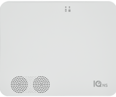
The front of the IQ4 NS includes 2 LED indicators, letting an installer or end user know the status of the system at a glance.
LED INDICATORS
Power LED
Solid Green
System is Powered by AC
Flashing Green
System is Powered by Battery Only. Loss of AC Power
Off
System is Powered Down
Status LED
Solid Green
Disarmed, Ready to Arm
Flashing Green
Ready to Arm but has open zones
Solid Orange
Trouble on the System
Flashing Orange
RF Jam Trouble
Solid Red
System Armed
Flashing Red
Alarm has occurred
Flashing Red (Rapidly)
Alarm has occurred, Bell silenced
Flashing Blue
Rebooting after Software Update
Solid Blue
IQ Installer Pairing Mode USING YOUR SYSTEM: KEYPADS
The IQ4 NS supports multiple different wireless keypads & keyfobs as well as the Alarm.com app. Depending on the system
configuration (PowerG, 319.5MHz, 345MHz or 433MHz), you can control the system using the following methods:
COMPATIBLE KEYPADS & KEYFOBS
Model
Frequency
Description
IQ Remote (QW9104-840)
Wi-Fi
Wi-Fi IQ Remote Touchscreen
IQ Remote PG (IQR-PG)
PowerG or Wi-Fi
PowerG IQ Remote Touchscreen
HS2LCDWF9
PowerG
2 x16 Wire Free LCD Keypad
PG9929
PowerG
4 Button Fob
PG9939
PowerG
4 Button Fob
PG9949
PowerG
2 Button Fob
FUNCTION KEYS & STATUS LIGHTS:
You can use shortcut keys to access options or features. Use the scroll keys to view the lit of options in each menu.
WIREFREE LCD KEYPAD
Status lights
Description
Ready - Indicates system normal. Must be on to arm the system. All zones must be
secured or bypassed and the system disarmed for this light to activate.
Armed- Indicates the system is armed. If the Ready light and the Armed light are both
on, an Exit Delay is in progress.
Trouble - On indicates a system malfunction or tamper. Flashing indicates that the
keypad has a low battery. Follow the instructions displayed or enter [*][2] to view the
trouble.
AC Power - Indicates AC Power is present. The AC Power light is off when AC is
absent.
KEYPAD STATUS LIGHTS AND KEYS
Key
Description
Stay arming arms doors and windows only.
Away arming arms doors, windows and motion detectors.
Chime turns exit sounds on and off.
Resets detectors to exit an alarm condition.
Quick Exit to exit the premises without disarming/rearming the system.
FUNCTION KEYS
NOTE: Press and hold function keys for two seconds USING YOUR SYSTEM: KEYPADS
Key
Description
Press and hold both keys simultaneously to generate a fire alarm.
Press and hold both keys simultaneously to generate a medical emergency alarm.
Press and hold both keys simultaneously to generate a panic alarm.
EMERGENCY KEYS
Action
Press
Arming and Disarming
Away arm
Press Away Arm for 2 seconds + [Access Code†]
Stay arm
Press Stay Arm for 2 seconds + [Access Code†]
Night Arm
When armed in stay mode [*][1] +
[Access Code†]
Disarm
[Access Code]
No-Entry Arming
[*][9] + [Access Code†]
Quick Arm /Quick Exit
[*][0]
Cancel arm Sequence
[Access Code]
Bypassing - All bypass commands begin with [*][1] + [Access Code†]
Bypass Individual Zones
[Three-digit zone #]
Bypass All Open Zones
[9][9][8]
Common Functions
Turn Chime ON/OFF
Change Brightness
[*][6] [Master Code] + [1][2] +
< >
Change Contrast
[*][6] [Master Code] + [1][3] +
< >
Buzzer Volume
[*][6] + [Master Code] + [1][4] +
< >
View Troubles
[*][2] + [Access Code†] +
< >
View Alarms
[*][3] + [Access Code†] +
< >
[*][4] + [Access Code†] or
ACTIONS
NOTE: † Access codes are optional based on security system installer configuration and whether secure arming is enabled.
USING YOUR SYSTEM: KEYPADS
ARMING AWAY WITH THE LCD KEYPAD
Away mode activates the complete alarm system by arming all perimeter sensors and arming all interior sensors.
To arm the system in Away Mode, complete the following steps.
1.
Ensure all windows and doors are closed and the Ready indicator is on.
2.
To arm using the Away key, press and hold the Away key for 2 seconds and, if required, enter your access code or to
Quick Arm the system press [*][0].
•
If zones are bypassed, the,
* Warning * Bypass Active
is displayed. After successfully initiating the arming
sequence, the armed indicator turns on and the Ready indicator remains lit. The Exit Delay timer begins counting
down. The keypad beeps six times, continues beeping every second until beeping rapidly in the final ten seconds.
•
The system can be configured to have a persistent exit delay that ends when the exit door is opened and closed,
or when a button is pressed outside the protected premises.
3.
To cancel the arming sequence, enter your access code. When the exit delay timer expires and the system is armed, the
Ready indicator turns off. The Armed indicator remains on and the keypad stops sounding.
NOTE: The installer configures the exit delay timer and whether or not an access code is required for arming the system.
ARMING STAY WITH THE LCD KEYPAD
Stay mode partially activates your alarm system by arming all perimeter sensors, and bypassing all interior sensors to arm
the system in Stay mode.
1.
Ensure all windows and doors are closed and the Ready indicator is on.
2.
Press and hold the Stay key for 2 seconds and, if required, enter your access code. Do not leave the premises.
3.
If zones are bypassed, the LCD keypad a warning is displayed. After you successfully initiate the arming sequence the
Armed indicator turns on. The Ready indicator remains lit.
4.
To cancel the arming sequence, enter your access code or present your proximity tag. When the exit delay timer expires
and the system is armed, the Ready indicator turns off and the Armed indicator remains on. The bypass or system
indicator activates.
NO ENTRY ARMING
No-entry arming arms the system in Stay mode by removing the Entry Delay from configured zones, arming all perimeter
sensors, bypassing all interior sensors. When you use the No-entry arming feature, an attempt to enter through a door or
window creates an instant alarm. To arm the system in No-Entry mode, complete the following steps.
1.
Check that the Ready indicator is on and your system is ready to be armed.
2.
Press [*][9] and, if required, enter your [access code].
3.
If zones have been bypassed, a warning message displays on the LCD keypad.
4.
After you successfully initiate the arming sequence the Armed light flashes as a reminder that the system is armed and
has no entry delay. The keypad sounds fast beeps. The keypad displays
Exit Delay in Progress
.
5.
To cancel the arming sequence, enter your access code. When the exit delay timer expires, the system is armed.
QUICK EXIT
Use the Quick Exit feature if the system is armed and you would like to leave without disarming and re-arming the system.
Quick Exit provides a two minute exit delay to leave the premises without triggering an alarm.
1.
When the system is already armed and the Armed light is lit, press and hold the Quick Exit key for 2 seconds or press [*]
[0].
2.
Exit the premises before the exit delay timer expires. After exiting, the delay timer is canceled. USING YOUR SYSTEM: KEYPADS
ARMING ERRORS
An error tone (long beep) sounds on the keypads if the system is unable to arm. Arming errors occur if:
•
The system is not ready to arm (i.e., sensors are open). and no Auto-bypass option is enabled on the IQ4 NS.
•
An incorrect user code is entered.
•
A trouble is present and has not been viewed by the user. This operation must be enabled by the installer.
To correct an arming error, complete the following steps:
1.
Ensure all sensors are secure. Your keypad identifies all open zones.
•
If the trouble light is on, enter [*][2] and enter [99] or scroll to the Acknowledge All Troubles prompt and press
[*], if your installer has configured your system to impede arming when a trouble is present.
•
Try arming the system again. For details on arming the system, see one of the previous arming procedures.
•
If errors persist contact your installer.
ARMING ERRORS AND EXIT FAULTS
The IQ4 NS audibly notifies you of errors when you are attempting to arm the system or exit the premises.
BYPASSING SENSORS
Warning: If a zone is not operating correctly, contact the installer immediately.
When you bypass a zone, protection is removed from specified zones the next time your system is armed. Bypassed zones
on an HS2LCD series keypad are indicated on the LCD screen as shown in the following table. If you use an icon keypad, the
bypass indicator lights and the bypassed zone numbers are displayed.
NOTE: For UL listed installations, zones can only be bypassed manually.
NOTE: Bypass Groups are no permitted in UL listed installations.
BYPASSED ZONES
•
Must be selected before arming the system
•
Allow for access to protected areas when the system is armed
•
Allow you to arm the system if a zone is temporarily out of service
•
Reduce the level of security
•
Do not sound an alarm
•
Are automatically canceled each time the system is disarmed
NOTE:
Bypass All Open Zones
allows the user to quickly bypass all open zones with a single command.
Clear Bypass
instantly clears all bypass conditions from the zones assigned to the partition. Ensure that no zones are unintentionally
bypassed when arming your system.
NOTE: For security reasons, your installer programs the system to prevent you from bypassing certain sensors, for example,
smoke detectors. For more information about fire sensors, see Fire and CO Zone Types.
LCD Display
Indication
Description
Zone Label < >
none
Zone is ready for arming.
Zone Label < > O
O
Zone is currently open. You cannot arm the system.
Zone Label < > B
B
Zone is bypassed.
LCD KEYPAD ZONE INDICATIONS USING YOUR SYSTEM: KEYPADS
BYPASSING INDIVIDUAL ZONES
1.
Press [*] to enter the function menu.
2.
Press [*] or [1]. If required enter your [access code] or present your proximity tag.
3.
Directly bypass zones by entering their [3-digit zone #]. If using an LCD keypad press [*] or scroll to the preferred zone
using the scroll keys and press [*].
4.
To toggle and unbypass a zone reenter the [3-digit zone #] or press [*] again. To bypass more zones repeat steps 3 and
4.
5.
To exit bypassing mode press [#], if the system is ready to arm the Ready indicator lights.
BYPASSING OPEN ZONES
1.
Press [*] to enter the function menu.
2.
Press [*] or [1]. If required, enter your [access code] or present your proximity tag.
3.
Press [9][9][8] OR scroll to Bypass Options using the keys and press [*]. Scroll to Bypass Op Zones and press [*].
BYPASS OPTIONS
[Auto Bypass = ON]
LCD Keypad: The burglary sensor is on. Press Stay or Away arm or enter the user code. The panel temporarily bypasses the
open sensor and arms. The LCD keypad displays
Warning Bypass Active
at the beginning of the exit delay for 3 sec and
bypass notification is received on user app.
NOTE: Auto Bypass is not permitted for UL Commercial Burglar Alarm use.
[Auto Bypass = OFF]
LCD Keypad: The burglary sensor is on. Press Stay/Away arm. The error tone sounds and the system does not arm. Select [*]
[1] and select “Bypass Open Zones”. The system is in temporary bypass mode for the next 2 minutes. If you are arming
during this time, any open sensor is automatically temporary bypassed and the ready LED flashes in the. The LCD keypad
displays
Warning Bypass Active
at the beginning of the exit delay for 3 seconds and the bypass notification is received on
the user app.
BYPASS GROUPS
1.
Press [*] to enter the function menu.
2.
Press [*] or [1]. If required, enter your [access code].
3.
Enter the three-digit zone number of the zones you want bypassed or scroll and press [*] to select zones.
4.
Press [9][9][5] to program the bypass group or scroll to
Bypass Options
and press [*].
5.
Scroll to
Program Bypass Group
and press [*]. The keypad beeps three times.
6.
Press [#] to exit
NOTE: Bypass groups must not be used in UL listed applications.
DISARMING THE SYSTEM WITH A KEYPAD
To disarm the system with an LCD complete the following steps.
1.
Enter your access code anytime the system is armed.
2.
If you walk through the entry door, the keypad beeps.
NOTE: The duration of the
Entry timer
is programmed by the installer. The installer will advise the maximum duration of
entry delay that was programmed in the system. For UL it cannot exceed 60 seconds. The system allows 254 seconds.
DISARMING ERROR
If your code is invalid, the system does not disarm and a 2-second error tone sounds. If this occurs, press [#] and re-enter
your access code. USING YOUR SYSTEM: KEYPADS
LCD KEYPADS EMERGENCY KEYS
Important: Only use in an emergency
If you press both the emergency keys you generate a fire, medical, or panic alarm, and you alert the monitoring station. To
generate a fire, medical, or panic alarm, complete the following step:
•
Press both alarm keys simultaneously for two seconds.
The keypad beeps to indicate that the alarm input is accepted and that an alert is sent to the monitoring station.
NOTE: Medical and panic alarms are audible by default. The installer can configure them to be silent.
NOTE: Only HS2LCD keypad models must be used for Residential Fire applications.
Verify with your alarm company that your system is equipped with emergency keys.
CHANGING THE BRIGHTNESS OF THE LCD KEYPAD
To change the LCD brightness, complete the following steps:
1.
On the keypad, press
* 6
.
2.
Enter your access code.
3.
Use the
Arrow
keys to navigate to
Bright Control
, and press
*
.
4.
Navigate to the brightness level that you want.
5.
Press
#
.
CHANGING THE CONTRAST OF THE LCD KEYPAD
To change the LCD contrast, complete the following steps:
1.
On the keypad, press
* 6
.
2.
Enter your access code.
3.
Use the
Arrow
keys to navigate to
Contrast Control
, and press
*
.
4.
Navigate to the contrast value that you want.
5.
Press
#
.
SETTING THE BUZZER VOLUME
NOTE: UL/ULC listed applications the keypad buzzer sound level must not be set to 0.
To set the buzzer volume, complete the following steps:
1.
On the keypad, press
* 6
.
2.
Enter your access code.
3.
Use the
Arrow
keys to navigate to
Buzzer Control
, and press
*
.
4.
Navigate to the volume level that you want.
5.
Press
#
.
Type
Key
Fire alarm
Medical alarm
Panic alarm
EMERGENCY KEYS USING YOUR SYSTEM: KEYPADS
If configured, you can arm or disarm the IQ4 NS system using the PG9929 or PG9939 wireless keys. Users who are in close
proximity to their premises can use wireless keys to arm and disarm their system, and to call for help.
NOTE: The panic feature has not been evaluated by UL for the PG9929/PG9939
ARMING THE SYSTEM
1.
Press the Arm button when the system is disarmed.
DISARMING THE SYSTEM
1.
Press the disarm button anytime the system is armed.
2.
If you walk through the entry door the keypad beeps, enter a valid user code before the entry delay expires.
NOTE: After
you disarm a system with an HS2LCD keypad using a 2-way wireless key, always check the alarm memory to
determine if any alarms have occurred during the armed period.
PG9929
PG9929 & PG9939 KEYFOB
Callout
Description
1
Away arm
2
Stay arm
3
Disarm
4
Panic
5
Command ouput 1
6
Message LED
7
Status LEDs
Callout
Description
1
Away arm
2
Stay arm
3
Disarm
4
Panic
5
Command ouput 1
6
LED
PG9939 USING YOUR SYSTEM: BASICS
Swipe down to
access settings
Touch an icon to
view its contents
Swipe left/right
to change pages
Navigation
Move from page to page and
access information on each
page using finger touches,
swipes, and scrolling.
Scroll up/down to reveal
additional content on a page
Dismiss
To dismiss a pop up when
you are done, swipe left or
right to dismiss.
Swipe a page away
when you are done
Note
: Weather is only
available when
enrolled via Wi-Fi.
IQ REMOTE & IQ REMOTE POWERG USING YOUR SYSTEM: MESSAGE CENTER
Contact
Easy access to your provider’s contact information, including phone
number, email, and website.
Alerts/Alarms
Alerts and alarms from your system like low battery alerts, alarms, and
power failures.
To dismiss, touch the circle to the left of the message and touch “OK” to
remove it from your message center.
You can also remove all messages at once by touching “Acknowledge All”
11/11/20
Message Center
Access your message center by touching the icon in the upper right corner. Once its open you’ll see two
sections: Contact and Alerts/Alarms.
(Note: This icon may appear different than shown, depending on your provider’s settings)
Messages
Messages from your provider will also appear here.
To dismiss, touch the circle to the left of the message and touch “OK” to
remove it from your message center.
You can also remove all messages at once by touching “Acknowledge All”
Note: This is only available when enrolled with Wi-Fi. USING YOUR SYSTEM: EMERGENCY PANIC
Emergency Panic
If you have a police, fire, or medical emergency and your system is not armed or a sensor has not been triggered, you can
send a manual emergency panic by touching the icon in the bottom right corner and selecting the type of emergency you are
experiencing. (
Note: based on your location, not all options may appear or be available to you.)
Alarm Types
Canceling an Emergency Panic
To cancel an emergency panic, touch the “cancel”
button and enter a valid user code.
X
Cancel
Police:
When touched it triggers the “Police”
siren pattern and sends a police emergency signal
to your provider’s monitoring station.
Emergency:
When touched it triggers the
“Emergency” siren pattern and sends an
emergency signal to your provider’s monitoring
station.
Fire:
When touched it triggers the “Fire” siren
pattern and sends a fire emergency signal to your
provider’s monitoring station.
To send a police or emergency panic
without sounding the siren, using the
“Silent Alarm” at the bottom of the screen Sensor status:
USING YOUR SYSTEM: ARMING
Arming Options
Quickly choose from “stay” or “away”
Touch to access
arming options
Sensor List
Open or active sensors
appear in a scrollable list
on the right. Touch the
icons in the upper right
corner to switch your view
to either “Active” or “All”
sensors.
?
Open
Closed
Active
Idle
Unreachable
Tampered
Synchronizing
See add’l options by touching
the “>>” icon on the right
Additional Arming Options
Select these options before choosing your arming type
Arming Stay
Arms doors and windows only
Arming Away
Arms doors, windows and motions
Additional Options
View additional arming options by touching the “>”
icon on the right side.
Bypass
Touch the circle next to a sensor to bypass it during
the arming sequence
Exit Sounds
The panel beeps as the timer counts down. Silence
these beeps before you choose the arming type.
Entry Delay
The panel will give you time to disarm once a “delay
door” has been opened. Turn this off with a touch. USING YOUR SYSTEM: DISARMING
Disarming your System
When your system is armed, there are multiple ways to disarm:
Disarming Manually
To manually disarm your panel, touch the icon in the center of the
screen. You will be prompted to enter a valid code. Failure to enter a
valid code with the time required will trigger the alarm.
Disarming Remotely
To remotely disarm your panel, login to your mobile app and touch the
“disarm” icon.
Download the
Alarm.com app
in the App store
or Google Play
Note: Remote disarming has not been evaluated by UL/cUL
Touch to disarm
panel manually ALARM EVENTS
Alarms
If the alarm is triggered the System will sound the
siren and display a red alarm screen.
Police
When the system is armed and the
alarm is tripped or you touch the
“Police” emergency button the alarm
sounds with the “Intrusion” siren.
Fire
When a Smoke or Carbon Monoxide
detector is triggered or someone taps
the “Fire” panic on the System the
alarm sounds with the “Fire” siren.
Emergency
When you press an IQ Pendant or
trigger an emergency signal from the
System, the alarm sounds with the
“Emergency” siren.
If your provider offers monitoring service, the panel
will automatically contact your monitoring center
using the dual path LTE and Wi-Fi connection.
To disarm, touch the screen and enter your passcode.
Preventing false alarms:
False alarms are a terrible waste of your public service resources, and can erode your relationship with local
authorities. In some areas, authorities even charge a fee for false dispatches.
Here’s some tips for avoiding false alarms:
-Use your system regularly, be comfortable with its operation.
-Make sure everyone who has access to your home has a valid access code and is familiar with how to use the
system.
-Ensure the doors you use the most are set up with delays to give you enough time to disarm the system when you
open a door.
-Test your system regularly
-Develop a routine.
-Use alternative methods for arming and disarming (mobile app, bluetooth disarming, etc.)
False Alarms
In the event of a false alarm, press disarm and
enter your user code. If your system is monitored,
be ready to provide your verbal password to your
security provider’s monitoring agent if they contact
you. If you are NOT able to provide the correct
verbal passcode, the authorities may be contacted. USING YOUR SYSTEM: SETTINGS
Settings Tray
Access common settings by swiping down
from the top of the screen.
Security Status
See your panel’s
security status in the
upper right. Touch it
to go directly to the
security page
Battery & Radios
Touch an icon to get more
information
-Battery level
-Wi-Fi connection
-PowerG Signal Strength
(PG enrollment only)
Volume
Slide left/right to
adjust the panel voice
Brightness
Slide left/right to
adjust the screen
brightness
Settings
Touch to access the
full settings page.
From there you can
also access “Advanced
Settings” (which will
require a passcode)
Photo Frame
Touch to access the photo
frame where you can
customize the panel’s
screensaver
Clean Screen
Disables the screen for 30 seconds
to allow you to clean it without
accidentally touching anything.
(
Touch the “standby” button on the
side of the panel to cancel)
Language
Touch to change panel
language
(only present on Wi-Fi
enrollment. For
PowerG enrollment, the
IQ Remote PowerG
follows the language
setting from primary
panel)
HOW TO ACCESS: SETTINGS: PHOTO FRAME
Photo Frame
When your panel is not in use, it turns into a customizable photo frame.
Settings
Inside settings you can choose whether you
want photos or a weather clock, if you want the
panel to turn itself off automatically in the
evenings, and more.
Note: Weather Clock is only
available on wi-Fi enrollment. USING YOUR SYSTEM: LIGHTS
Light Control
You can add Z-Wave lights, lamp modules, or lightbulbs to your primary panel. This will allow you to control
your lights locally on the panel, IQ Remote PowerG, and also from your mobile app. Once your first light is
added to your system, the lights page will appear. Simply swipe over to access it.
ON
Touch turn on all
selected lights
OFF
Touch turn off all
selected lights
GET STATUS
Touch to check the
status of all selected
lights
Select
Touch the circle next
to a light to select it
Energy
Touch the energy icon to see how much energy the
outlet is currently using
Dimmer
Touch the
slider from left
to right to
adjust the
brightness of a
single dimmer
ON/OFF
Touch a bulb or
outlet icon to
turn it on or off
LIGHT ON
LIGHT OFF
SMART SOCKET ON
SMART SOCKET OFF
Mobile Access
You can also control your lights from your mobile app. USING YOUR SYSTEM: LOCKS
Lock Control
You can add Z-Wave locks to your primary panel. This will allow you to control your locks locally on the
primary panel, IQ Remote PG and also from your mobile app. Once your first lock is added to your system, the
lock page will appear. Simply swipe over to access each one.
UNLOCK ALL
Touch to unlock all
your locks at once
LOCK ALL
Touch to lock all
your locks at once
Get Status
Touch the refresh
icon to check the
lock’s current status
ON/OFF
Touch the key
icon to unlock
or lock it
Change Locks
If you have
more than one
lock, swipe up
and down to
access each
one.
UNLOCKED
Mobile Access
You can also control your
locks from your mobile app.
LOCKED USING YOUR SYSTEM: THERMOSTAT
Mode
Touch to change this thermostat
from heat to cool (or off) or use
“automatic” which switches from
heat to cool as needed to maintain
your target temperature.
Current Temp
Displays the current
temperature in your
home
Fan
Touch to change
to “On” or
“Automatic”
Up/Down
Touch the
arrows to
adjust the
target
temperature
Switch
If you have
more than one
thermostat,
swipe up and
down to
access each
one.
Mobile Access
You can also control your
thermostat from your mobile app.
Thermostat Control
You can add Z-Wave thermostats to your primary panel. This will allow you to control the temperature in your
home locally on the primary panel, IQ Remote PG and also from your mobile app. Once your first thermostat
is added to your system, the thermostat page will appear. Simply swipe over to access it. If you have more
than one thermostat swipe up and down to access each one.
Battery level
Displays how much
battery is left in
your thermostat USING YOUR SYSTEM: GARAGE DOOR
Garage Control
You can add up to Z-Wave garage door controllers to your primary panel. This will allow you to control your
door locally on the primary panel, IQ Remote PG and also from your mobile app. Once your first garage
opener is added to your system, the garage page will appear. Simply swipe over to access each one. If you
have more than one overhead garage door swipe up and down to access each one.
GARAGE CLOSED
GARAGE OPEN
Open/Close
Touch the icon
to open or
close the
garage door
Switch
If you have
more than one
garage door,
swipe up and
down to
access each
one.
Open
Touch the icon
to open the
garage door
(not available
when the
garage door is
already closed)
Close
Touch the icon
to close the
garage door
(not available
when the
garage door is
already closed)
OPEN ALL
CLOSE ALL USING YOUR SYSTEM: LIVE VIEW
Live View
Easily view the live video feed from your Alarm.com video cameras on the 7” panel screen. This page will
appear automatically if cameras are added to the account and the authorization has been given on the
Alarm.com customer website. Supports live view of up to 40 cameras. Supported models: ADC-V521IR, ADC-
V522IR, ADC-V622, ADC-V722W, ADC-VC725, ADC-VC726, ADC-VC825 & ADC-VC826.
Camera View
A thumbnail of
the camera will
be displayed for
the highlighted
camera. Click the
play button to
view full screen.
Cameras List
All supported
cameras that are
on the account
and have been
authorized will
show here. Click
the camera you
would like to
view.
Exit
Click on the
red X icon to
exit full screen
mode.
Camera View
Full screen mode
can be activated
by clicking on
the play button
for each
individual
camera.
Important Note
Cameras will only
push to your panel
if you have
authorized them to
do so from your
Alarm.com
customer website.
This can be found
under Video
Settings.
Note
: Live View is only available when enrolled via Wi-Fi. OPTIONAL SETTINGS: SCENES
Alarm.com Scenes
If enabled by your dealer, Alarm.com Scenes allow you to
control multiple devices with the click of a single button
right from your touchscreen. Each option is a multi-
device command that coordinates different smart
devices to accomplish a complex task. Smart Scenes
must be setup and customized from your Alarm.com
customer portal before they can be used from the panel.
Alarm.com Scenes
Setup your Scenes from your
Alarm.com customer site. When
logged in, navigate to the Automation
tab. Here, you will be able to build
custom scenes that control multiple
smart devices within your home.
Note
:
Scenes are
only
available
when
enrolled via
Wi-Fi. USING YOUR SYSTEM: PARTITIONS
Alarm.com
Partitions control can
be accessed from the
Alarm.com customer
site as well from your
mobile app.
PARTITIONS
Partitions are enabled on the primary panel. Any area or zone that needs to be armed or disarmed separately
from the rest of the structure can be turned into a partition. Partitions allows for the creation of zone groups in
a home or building so that users can arm some sections of the property while leaving other areas disarmed.
Partitioning enables greater personalization and functionality while simplifying installation.
Each IQ Remote PowerG can be assigned to support only 1 partition on the primary panel. It controls its local
zone status, alerts and notifications.
!
Important Note:
If 6-digit codes are enabled in the panel but not changed in User Management,
the panel will add two Zeros to the end of the original code. Example: If original user code is 1234 and 6-
digit codes are enabled but the user code isn’t changed, the new user code will be 123400.
Exclusions:
You cannot partition Z-Wave or Alarm.com cameras today. This functionality will come at a later date via software update. Global
sounds and sirens can be turned on from the Sound menu when partitions are enabled. When global sounds and sirens are turned on,
all sounds and sirens will sound across all partitions. LEGAL
FCC REGULATORY INFORMATION
This device complies with Part 15 of the FCC Rules. Operation is subject to the following two conditions: (1) This device
may not cause harmful interference, and (2) this device must accept any interference received, including interference
that may cause undesired operation.
NOTE: This equipment has been tested and found to comply with the limits for a Class B digital device, pursuant to
Part 15 of the FCC Rules. These limits are designed to provide reasonable protection against harmful interference in a
residential installation. This equipment generates, uses and can radiate radio frequency energy and, if not installed and
used in accordance with the instructions, may cause harmful interference to radio communications. However, there is
no guarantee that interference will not occur in a particular installation. If this equipment does cause harmful
interference to radio or television reception, which can be determined by turning the equipment off and on, the user is
encouraged to try to correct the interference by one or more of the following measures:
—Reorient or relocate the receiving antenna.
—Increase the separation between the equipment and receiver.
—Connect the equipment into an outlet on a circuit different from that to which the receiver is connected.
—Consult the dealer or an experienced radio/TV technician for help.
This equipment complies with radiation exposure limits set forth for uncontrolled environment. The antenna(s) used
for this transmitter must be installed to provide a separation distance of at least 27 cm from all persons and must not
be collocated or operating in conjunction with any other antenna or transmitter.
IMPORTANT: Changes or modifications not expressly approved by Qolsys, Inc. could void the user’s authority to
operate the Product.
IC REGULATORY INFORMATION
This device complies with Industry Canada license-exempt RSS standard(s). Operation is subject to the following two
conditions: (1) this device may not cause interference, and (2) this device must accept any interference, including
interference that may cause undesired operation of the device.
Cautions:
1.
Devices operating in the 5150-5250 MHz frequency band are restricted to operate in-door only.
2.
Operation in the band 5150–5250 MHz is only for indoor use to reduce the potential for harmful interference
to co-channel mobile satellite systems.
3.
Users should also be advised that high-power radars are allocated as primary users (i.e. priority users) of the
bands 5250-5350 MHz and 5650-5850 MHz and that these radars could cause interference and/or damage
to LE-LAN devices.
Cet appareil est conforme aux normes d’exemption de licence RSS d’Industry Canada. Son fonctionnement est soumis
aux deux conditions suivantes : (1) cet appareil ne doit pas causer d’interférence et (2) cet appareil doit accepter toute
interférence, notamment les interférences qui peuvent affecter son fonctionnement
CAN ICES-3 (B)/NMB-3(B)
Cet équipement est conforme aux limites d'exposition aux rayonnements IC établies pour un environnement non
contrôlé. Cet équipement doit être installé et utilisé avec un minimum de 27 cm de distance entre la source de
rayonnement, votre corps, et d’autres antennes ou transmetteurs. LEGAL
Avertissement:
1.
Les dispositifs fonctionnant dans la bande 5 150-5 250 MHz sont réservés uniquement pour une utilisation à
l’intérieur.
2.
Les dispositifs fonctionnant dans la bande 5 150-5 250 MHz sont réservés uniquement pour une utilisation à
l’intérieur afin de réduire les risques de brouillage préjudiciable aux systèmes de satellites mobiles utilisant les
mêmes canaux
3.
De plus, les utilisateurs devraient aussi être avisés que les utilisateurs de radars de haute puissance sont
désignés utilisateurs principaux (c.-à-d., qu’ils ont la priorité) pour les bandes 5 250-5 350 MHz et 5 650-5
850 MHz et que ces radars pourraient causer du brouillage et/ou des dommages aux dispositifs LAN-EL.
FCC/IC STATEMENT
Changes or modifications not expressly approved by Qolsys can void the user’s authority to operate the Product. This Product has
been tested and found to comply with FCC Rules.
This Product generates, uses, and can radiate radio frequency energy and, if not installed and used in accordance with the
instructions, may cause harmful interference to radio communications. However, there is no guarantee that interference will not
occur in a particular installation.
If this Product does cause harmful interference to radio or television reception, which can be determined by turning the
equipment off and on, the user is encouraged to try to correct the interference by one or more of the following measures:
1.
Reorient or relocate the receiving antenna.
2.
Increase the separation between the Product and receiver.
3.
Connect the affected equipment and the Product to separate outlets, on different branch circuits. Consult the dealer or an
experienced radio/TV technician for help.
Household Fire Safety Audit
Read this section for important information about fire safety. Most fires occur in the home. To minimize this danger, we
recommend that a household fire safety audit be conducted and a fire escape plan be developed.
1.
Are all electrical appliances and outlets in a safe condition? Check for frayed cords, overloaded lighting circuits, etc. If you
are uncertain about the condition of your electrical appliances or household service, have a professional evaluate these units.
2.
Are all flammable liquids stored safely in closed containers in a well-ventilated cool area? Cleaning with flammable liquids
should be avoided.
3.
Are fire-hazardous materials (e.g., matches) well out of reach of children?
4.
Are furnaces and wood-burning appliances properly installed, clean and in good working order? Have a professional
evaluate these appliances.
Fire Escape Planning
There is often very little time between the detection of a fire and the time it becomes deadly. It is thus very important that a
family escape plan be developed and rehearsed.
1.
Every family member should participate in developing the escape plan. LEGAL
2.
Study the possible escape routes from each location within the house. Since many fires occur at night, special attention
should be given to the escape routes from sleeping quarters.
3.
Escape from a bedroom must be possible without opening the interior door.
Consider the following when making your escape plans:
1.
Make sure that all border doors and windows are easily opened. Ensure that they are not painted shut, and that their locking
mechanisms operate smoothly.
2.
If opening or using the exit is too difficult for children, the elderly or handicapped, plans for rescue should be developed.
This includes making sure that those who are to perform the rescue can promptly hear the fire warning signal.
3.
If the exit is above the ground level, an approved fire ladder or rope should be provided as well as training in its use.
4.
Exits on the ground level should be kept clear. Be sure to remove snow from exterior patio doors in winter; outdoor
furniture or equipment should not block exits.
5.
Each person should know the predetermined assembly point where everyone can be accounted for (e.g., across the street
or at a neighbor's house). Once everyone is out of the building, call the fire department.
6.
A good plan emphasizes quick escape. Do not investigate or attempt to fight the fire, and do not gather belongings as this
can waste valuable time. Once outside, do not re-enter the house. Wait for the fire department.
7.
Write the fire escape plan down and rehearse it frequently so that should an emergency arise, everyone will know what to
do. Revise the plan as conditions change, such as the number of people in the home, or if there are changes to the building’s
construction.
8.
Make sure your fire warning system is operational by conducting weekly tests. If you are unsure about system operation,
contact your installer.
9.
We recommend that you contact your local fire department and request further information on fire safety and escape
planning. If available, have your local fire prevention officer conduct an in- house fire safety inspection.
- Uploaded