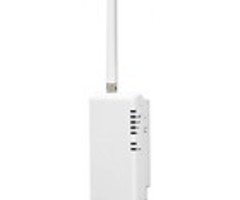
Telguard HomeControl Flex with DSC Power Series (PC1616 / PC1832 / PC1864) - Install Guide
Related Products


Related Categories
Document Transcript
Rev 2
.0
1
© 2015 Telguard
HomeControl Flex
Installation: TG
-
1 Express with DSC
1832
The
following information is to serve as a guide for installations of TG
-
1Express devices enabled for
Interactive Services with the DSC
1832
. The configuration shown in the diagram below is an example of how
a proper installation could look. The output and z
one could differ from the diagram, without changing the
outcome of the installation.
Installation Diagram
STC
STC
TRIP IN
GND
DC
+
AC AC Aux
+
Aux
-
Bell
+
Bell
-
RED BLK YEL GRN
PGM
1
PGM
2
PGM
3
PGM
4
Z
1
COM Z
2
Z
3
COM Z
4
Z
5
COM Z
6
Z
7
COM Z
8
EGnd R T R
1
T
1
PC
1864
Only
PC
1832
PC
1864
Only
Power Series
PC
1616
/
PC
1832
/
PC
1864
PC
-
LINK
1
:
Ring return
2
:
GND
3
:
STC
4
:
Ring
5
:
Tip
6
:
STC
7
:
DC
+
8
:
Tip return
Note:
Although a resistor is not depicted here, one may be required by the Keyswitch zone in accordance to the
Panel’s sp
ecifications. For more information, please refer to the Panel’s Installation and/or Programming Manuals.
Rev 2
.0
2
© 2015 Telguard
Programming Steps
After getting into configuration mode, check/do the following:
Program Keyswitch
zone
:
Program Output
:
Enable Open/Close Reports:
Set
to
Contact ID:
Reference Note
For more detailed TG
-
1B and TG
-
4 installation and programming instructions, refer to the
HomeControl Flex Installation Guide.
- Uploaded
