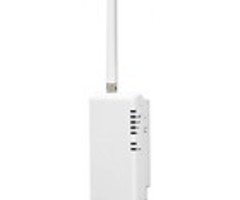
Telguard HomeControl Flex with NetworX NX6/NX8 - Install Guide
Related Products


Related Categories
Document Transcript
Rev
2
.
1
1
© 201
6
Telguard
HomeControl Flex
Installation: TG
-
1 Express with
GE
NX6
The
following information is to serve as a guide for installations of TG
-
1Express devices enabled for
Interactive Services with the
GE
NX6
.
The configuration shown in the diagram below is an example of how a
proper installation could look. The output and zon
e could differ from the diagram, without changing the
outcome of the installation.
Although the
NX8
panel is very similar, there may be some variations in
programming. However, the concepts remain the same.
Installation Diagram
STC
STC
TRIP IN
GND
DC
+
1
:
Ring return
2
:
GND
3
:
STC
4
:
Ring
5
:
Tip
6
:
STC
7
:
DC
+
8
:
Tip return
Note:
Although a resistor is not depicted here, one may be required by the Keyswitch zone in accordance to the
Panel’s specifications. For more information, please refer to the Panel’s Installation and/or Programming Manuals.
Rev
2
.
1
2
© 201
6
Telguard
Programming Steps
After g
etting into configuration mode, check/do the following:
Program Keyswitch
zone
:
Program Output:
Enable Open/Close Reports:
Rev
2
.
1
3
© 201
6
Telguard
Set to Contact ID:
N
X8E Hardware Variation
T
he location of the Aux Out connections is different for the NX8E panels.
Plea
se
l
ook at
the
diagram below for reference
:
Technical
Note
When the panel utilizes 4
-
wire smoke detectors,
its
outputs may work differently than expected
,
and become incompatible with the
HomeControl Flex
solution
. If the output does not work as it
should, contact Technical Support for the
Alarm P
anel
M
anufacturer to understand the limitations
of using an output
for Armed Status alongside
4
-
wire smoke detector
s
versus 2
-
wire detectors
.
Reference Note
For more detailed TG
-
1B and TG
-
4 installation and programming instructions, refer to the
HomeControl Flex Installation Guide.
- Uploaded
