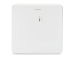
LTEM PA/PV: Wiring to Share Panel Power
Related Products


Description
In this video, Griffin from Alarm Grid shows the viewer how to wire the LTEM-PA or LTEM-PV so that it gets all its power from the ...
Transcript
[AUDIO LOGO] Hey, DIYers. Griffin with Alarm Grid here. And today, we're going to go over doing the shared power connection method with an LTEM-PV in a VISTA residential system. So let's go ahead and let's get to it. So the tools that we're going to use today for this installation is some pair of wire strippers for stripping the wires and just a small flat tip screwdriver for the screws on the panel and on the communicator itself. And then the wire we're going to use is 18 gauge, 4 conductor wire. We're going to assemble the communicator first before we mount it on the panel. So here, there is usually a little plastic piece that can be broken out. And what we're going to put there is this little threaded piece into this part right here. And then what this is going to be used for is, whenever you mount it on top of the panel, you screw this inside of the panel onto this little bracket here to tighten it down so it doesn't move. So let's go ahead and start with wiring on the communicator. We're going to start with the black and red wire. Now, on the communicator, on the screw terminals, you will see plus 9 volts, and then GND which stands for ground. My red wire is going to go into the plus 9 volts. My black wire is going to go into the ground connection. Make sure the ground connection is loose. I'm going to slide these in here. I'll tighten them down. So the next two wires we're going to concentrate on is the green and white wire. Now, sometimes, you may get a 4 conductor. Instead of having a white, you'll have a yellow wire instead of a white wire. The most common one is yellow. But today, we've got a white one. So what we're going to do is put the green wire into the TX terminal, which is labeled with a T in front of the terminal. And then the white wire is going to go into the R terminal connection. The screws are already loose, so we're going to make those connections real quick. We're going to scoot it in here to make sure it's in there, so there will be a little bit better connection. And the screw will have a better hold on it. I'm going to put the white in. Just kinda scoot that in there. I'll tighten it down. Now, once you have your wire securely in there, you want to make sure to run your wire through this bracket here because that's going to go into the panel. And that way, the wire will go into the panel as well. So that way, you can close the lid and close the panel whenever it's securely done. We'll leave it like that right there. So the panel that we're using to demonstrate the connection is a VISTA-21iP. You're going to use the exact same screw terminals on the 21iP on the VISTA-20P and 15P as well. Now, the big difference between the 21iP and the other two is we've got a jumper that we need to move from the top and middle pin and bottom middle pin, because the 21iP has an internal communicator. And if we're no longer using that, the system must be powered down removing the AC connection and battery before moving this pin. And the pin is right below the IP port here. And you see it's on the top and middle, so we're just going to simply unplug it. And you see those three pins. And then we're going to move the pin to the bottom and middle pin. This 21iP is now ready to use external communication. And next, we're going to run our wires into the panel through this hole here. We're going to put the metal ring that will help hold the communicator to the metal panel here-- metal can. I'm going to slide this in. Then put this on here. Try not to cross thread it. Oh. I'm going to tighten that up-- hand tight, as tight as it'll go. And then that will hold your communicator onto the panel. So now on the panel, the screw terminals are labeled. We're going to be looking at terminals 4, 5, 6, and 7. But on the residential panels you'll see they're labeled. We're going to go to terminal 4. Again, GND stands for ground. That's going to be a black wire. On this one it's labeled AUX. So this is 12 volts. This is where your red wire will go. Then of course, you will see green for terminal 6. And then yellow-- which we don't have a yellow wire. We're using the white wire in this case. So we're going to start. I'd like to get them organized and the way they're going to go. Let's start with the red wire and black wire first as soon as I get them straightened out here. I'm going to hold those in place. I'm going to tighten them down. Then again, the green terminal 6 here, and then the yellow or white, depending on what color you have on your wires. So now again, the way we have wired up, black goes to terminal 4, red goes to terminal 5, green goes to terminal 6, and yellow or white goes to terminal 5. Now, the main thing is, on the communicator, it says 9 volts. But it's able to take 9 volts or 12 volts. The only time you could use the 12 volts is if you're doing the shared power method because terminals 4 and 5 is 12 volts DC. It's a little side note. And that's how you connect an LTEM-PV on shared power method into a VISTA residential system. If you have any questions, you can send us an email to support@alarmgrid.com or reach out to us at our website alarmgrid.com. If you found this video helpful, please hit the Like and Subscribe button. And don't forget to hit that bell at the bottom for future notifications for future videos. I'm Griffin with Alarm Grid. And I'm happy to help.
- Uploaded
