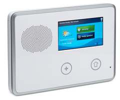
How do I add a wired siren to Go!Control 2?

The Altronix RBSNTTL is a sensitive, low-current relay often used on panels with a low current bell output or trigger. It is used to activate a higher current device, such as an outdoor siren. In the diagrams below, you can see two different ways to properly wire the RBSNTTL for this purpose. Because we're using the panel's existing low current bell output, no separate programming is required. Any zone that would normally activate the bell output in an alarm condition, will activate the relay, and sound the external device. Alarm Grid sells a kit, which we put together, and which contains the RBSNTTL, an AD12612 1.2 Amp power supply with Transformer, 4 AH battery, and a metal enclosure to mount it all in. Just add the siren of your choice. This kit was originally configured to work with Honeywell's Lynx Touch panels, but will work fine with the 2GIG Go!Control 2.

In this diagram, we show using the Bell negative as a trigger, with the RBSNTTL's positive trigger strapped to a constant positive power source. This method is preferred because it uses less wire.


The wiring shown below will achieve the same result, but requires that an extra wire be run from the 2GIG GC2 to the Altronix relay. Even when using the bell output Bell Negative and Bell positive to the triggers, you still must have a common negative between terminal two (2) on the 2GIG GC2 and the DC negative on the power supply.


Battery Note: This diagram doesn't show any particular 12 Volt DC Power supply. These power supplies come in various shapes and sizes. Some will have screw terminals to which the battery negative and positive tabs are connected. Others, like the AD12612 will have flying leads coming off the circuit board, with spade lugs that connect to the battery tabs. This diagram is simply intended to show that the power supply, like any device that has its own connection to AC power, should have a backup battery to keep it running when AC power is lost. Below is a drawing of the AD12612, showing the proper battery leads.


Did you find this answer useful?

We offer alarm monitoring as low as $10 / month

Click Here to Learn More
Success! I didn't have Q78 programmed correctly. I changed to 08 and now everything is working great! Thank you Julia and team! This is the only place on the internet that discusses how to wire the siren into the GC2
Hi Joe, I set this up initially when I tested this, but it's been taken apart since then. It sounds like your panel's bell circuit is not working properly. Under normal circumstances, the bell positive is always hot (meaning if you meter bell positive to DC negative, you'll have voltage there) and it's the bell negative that is either connected to ground (when an alarm occurs) or not connected to ground (when there is no alarm). In your case, it seems like maybe the bell negative is always connected to ground. That's just not normal. There is programming for the open collector in Q78 on the GC2 I believe, that will allow you to tell it you want it to activate for all alarms, for burglary only, for fire only, or as an internal sounder (that sounds like what you have it set for now). Set the Open Collector just to activate on alarms, and that should solve your problem. Q78, programmed as 08 should do it.
https://uploads.disquscdn.com/images/7950f87d8cc324e536a284cc0730dce708e6f9960ed902043ce15ad6b005f645.jpg https://uploads.disquscdn.com/images/b3b1b66a54d5030c0d952a76c9f123cfb6fb1c3459021991bff51bdde41c6ec2.jpg
Hi Julia. I’m back at it. Nope, nothing else is connected to the panel’s bell output. There is a speaker/siren mounted inside the control panel, but nothing wired into the bell terminals. My main thing I can’t get past is the “trigger” source. When I test all of the configurations illustrated here, I never find a change of state using my multimeter. For example, the Bell +/- terminals on my panel always have continuity in both the non-alarm and alarm state. Same thing using the Bell(-) and the DC(-) configuration...always in the same state. I had this same issue at my previous home with a different panel. I had success in using the Bell(+) and Open Collector as described by Jonathan. This would activate the relay and sound the siren sirens. However...the wired sirens are also being activated with any alert. My neighbors are going to kill me if the sirens chirp every time there is a low battery or loss of supervision. What do you think? Any ideas? A picture of the wiring that’s working is attached
This worked for me. But don't forget to change Q78 in the programming to 08
Thank you for that information. I appreciate your feedback.
I am using a 40VA transformer right now and it is providing sufficient power to run 1.7A of load. If you get into the weeds on the Altronix website, the 40VA wall wart transformer will run the SMP3 at 6V and 12V, but you have to move up to the open frame transformer for 24V. In my experience, the 40VA transformer has been fine for my needs.
Hi Matthew, I'm sorry this question has gone unanswered for a while. According to the Altronix website to get the full power output from the SMP3 you need a 55.2VA transformer. I believe this was changed by Altronix after we posted our product description. We will get this updated ASAP. In the meantime, I don't think we currently sell a transformer with these specs (I can't even find a suitable transformer listed on the Altronix website. Their transformer is also a 40VA. According to the specs on the SMP3 data sheet, Input Voltage can be 16VAC to 28VAC. There is no VA rating listed on the spec sheet, but it is listed on their website <a href="https://www.altronix.com/products/SMp3">here</a>.
After further troubleshooting, I have now got the system working. I have a long 18ga wire run going to the attic for a siren (no siren is currently there) that was wired in parallel with the indoor WBOX siren. I had shorted that wire run while identifying and labeling the wire runs. After unshorting that wire run, the system now works. I am looking forward to getting my Honeywell 748 from you guys to place in the attic.
I recently ordered an RBSNTTL and a WBOX 0E-SIRENSTRObe from Alarmgrid and am attempting to connect it to my 2GIG GC2 panel. The panel is powered by the included 2GIG-AC1 power supply on inputs 1 and 2 on the panel. The siren/strobe and RBSNTTL are being powered by an Altronix SMP3 power supply. I have connected the Trigger+ to Bell+, Trigger- to the Open Collector, the SMP3 to Pos+ and Neg-, jumped Pos+ to C, and the siren is wired to positive NO and negative siren wire directly to Neg- on RBSNTTL. Question 78 is set to follow any alarm. When my alarm goes off, my panel siren will go off and continue sounding, but my WBOX siren/strobe will only alert for 2-3 seconds, then stop sounding or lighting. The RBSNTTL continues to make clicking and humming sounds while the panel siren is sounding, but no power is being passed to the siren/strobe and it won't do anything. Is this a fault with the RBSNTTL? I am unsure why the siren/strobe will go off for 3 seconds then stop as the panel siren continues to alarm and the RBSNTTL clicks away. The SMP3 is also powering 3 Take-345's, a PIR, a Glass Break sensor, and is powered by a 16.5VAC, 40VA transformer.
Are you connecting anything other than the relay to the panel's bell output?
Hey guys. I actually tried all this 3 years ago and didn’t have any luck and gave up. I moved and am trying again, but having no luck. I’ve tried all three wiring options listed on here. The main issue I’m encountering when trouble shooting is that I can’t register a change on my multimeter at the panel when it goes into an alarm mode. I’ve tried all three panel-side configurations and my Q78 is set to follow. I figure the issue squarely lies in getting a change in state from the panel. If anyone has a picture of an actual installation that works that would be fantastic!
Did you try them and they didn't work? You can use the open collector as you outline, but you don't <i><b>have</b></i> to. In fact, further down this board, I have a diagram showing how to wire using the open collector. The 2GIG GC2 and GC2e both use a negative bell trip, which, when you have a common negative (DC - as shown in the first diagram) should work as a negative trigger. Since the bell is a negative trigger, Bell + is always hot, so I have it wired to Trig + on the RBSNTTL. You could also just strap a Jumper from Power Positive on the RBSNTTL to Trig +. Again, as long as you have the common negative with the panel.
I am sorry to say that neither of these is correct for the 2Gig GC2 panel. I was troubleshooting an installation with the RBSNTTL and GC2 and discovered that you need to use wired ports 4 and 5 Bell + and Open Collector to make this work correctly. Use port 4 Open Collector for the Negative wire to the Trigger negative on the RBSNTTL.
I will give this a try in a day or two and report back, thank you for the input.
Here's a quick diagram Julia put together to show how to wire it using the open collector. Can you give that a try and report back? Be sure and program Q78 in the programming to match as well (as noted in the diagram). https://uploads.disquscdn.com/images/afa04d9d79fa3592878b5af853c0d2dc7ea5708de97d835f018de3846beb1e53.png
I used the top wiring diagram.
Which of the two diagrams above did you use?
I realize this may be an old discussion, but I just got around to doing this. And i am having the same problem as most. Wired exactly like shown above (re-wired 5 times) and I have constant 12v on NO of relay. The only difference is I also have a 2GIG TAKE-KIT1 using the same battery, power supply and ac input. I noticed there is another article on your website https://www.alarmgrid.com/faq/can-i-use-a-wired-siren-with-a-2gig-gocontrol that mentions using the "Open collection" I was wondering if there is a wire diagram for this solutions.
Are you sure you have the jumper wire between Trigger + and Power positive? If that connection is missing, this won't work. No special programming is required, that's why using the panel's bell output is recommended. In order to use terminals 5 and 6 you'd need a different model relay. The Altronix RB5. If you'd like to send in some good pics of your wiring to support@alarmgrid.com we can take a look at it.
Thanks for the quick response. I've tried this arrangement numerous times and I'm having no luck. The siren sounds whether there is an alarm or not. I used a multi meter to verify no continuity between terminals 2 and 6 when there is no alarm and there is continuity between 2 and 6 when there is an alarm. So, my panel is not malfunctioning. Are there any programming settings that need to be changed in the panel? Could you also provide a diagram using terminals 5 and 6 for the GC2? Thanks
The diagram in the FAQ was updated after we verified that this setup works. The GC2 uses a negative bell trip while the GC3 uses a positive bell trip. The original diagram on this FAQ assumed the GC2 also used a positive bell trip. It has since been edited to show the correct information (meaning the FAQ diagram is now the same as the one I created for Joe).
Hi, i don't think this diagram is any different than the first one you posted. Could you verify it's correct?
The GC2 has a negative trip bell output. That means Bell positive (terminal 5) is always hot when metered with the panel ground. When the bell output is activated, the Bell negative (terminal 6) connects to ground to provide bell voltage. When there is no alarm condition, you should be able to check for continuity between Ground (terminal 2) and Bell negative (terminal 6) and show an open circuit. When there is an alarm occurring where a bell should sound then you should have continuity between the Bell negative and Ground. If you have continuity between Bell negative and ground when there is no alarm, then I'd say that's potentially a bad panel.
Thanks Julia. I'm trying to connect a wired siren to a 2gig GC2. I used the diagram above and my siren keeps sounding even when there is no alarm. Im using the same relay and a honeywell 1.2A power supply. I've been told that having voltage across terminals 5 and 6 is normal. Can you confirm the diagram is correct? Any suggestions? Thanks!
According to page 15 of the GC2 installation instructions, the bell circuit provides 6 - 12 volts DC, and can be supervised. If the device you're connecting to the Bell positive and Bell negative is a a very low current draw, you should install an 820 ohm resistor in parallel with the bell circuit to prevent the sounder from making noise while in a non-alarm state.
Hi, I have a constant voltage across the bell+ and bell- terminals on a 2gig gc2. So, its causing the siren to go off whether there is an alarm or not. Do I need to add a resistor to the bell- side. Is there something to turn off in the configuration to prevent this? Is the panel broken?
Sure, feel free to give us a call at the number at the top of the webpage or at 888-818-7728. Our office hours are 9am-9pm EST Monday-Friday.
Give me an opportunity to talk about it, since the system is going to be installed in our personal office and the decision is not mine alone, I get in touch.
Are you interested in having us monitor your system? Do you have an Alarm.com module installed in your system? We have no-contract monitoring plans online at https://www.alarmgrid.com/monitoring and are experts on that system.
I have 2gig gc2
As long as your setup isn't over-drawing your power supply, that should work. Which alarm system are you using?
Can I add a 12vdc, 4.3 amp light beacon to the siren connection? so that he can also light up with the siren? my voltage source is 12 vdc, 8.5a
The LYNX-WEXT kit should allow you to interface a hardwired siren with the IQ2: https://www.alarmgrid.com/products/alarmgrid-lynx-wext
Is there anything like this for the Qolsys IQ Panel 2? I'd love to run the POTTER SSX52SC strobe/siren off of it but the Qolsys can only handle 12v/300mA...
Since you have a common negative, you could wire it that way, the way shown is just a little simpler, and uses less wire. It doesn't offer any more supervision of siren wiring than your way would. The only reason for the connection to the positive trigger at all is due to the note shown in the RBSNTTL Install Instructions: https://www.alarmgrid.com/documents/altronix-rbsnttl-installation-instructions
Just out of curiousity, why can't the Bell - and Bell + be wired directly to the trigger of the relay? And the power supply to the Pos and Neg with jumpers to their respective C terminals? Is this wiring you show simply so you can have supervision on the siren wiring?
We can takeover the monitoring on your system and we offer low cost, no-contract plans online at https://www.alarmgrid.com/monitoring. Do you know the current firmware version of your Vivint branded GC2 panel?
Hey guys. Was out of country for a little while. But back on this panel situation. Still haven't gotten it to work. But I finally hooked up the multimeter to the panel and, sure enough, i think the problem in my case is that the two "bell output" terminals on the panel always have voltage regardless of whether the siren is activated or not. No change in behavior. Which is obviously a problem. Since Vivent locked me out of the toolbox (default installer code isn't working), I've got to get someone to monitor it and unlock it so i can maybe use the open collector. Will report back once all that gets straightened out to confirm the wiring. Thanks again!
Joe, diagram has been corrected, give this a try and let me know if that corrects the issue. https://uploads.disquscdn.com/images/923d0dd339f1284bba714bcff0a7e86f69d8d906aef8cb7f416a140a3b51e7b6.png
Hi Joe, I put this together, and I did so assuming that the GC2 and GC3 bell outputs behaved the same way, but they don't, and I found that out based on what you're seeing here. So thank you for helping me find this. Give me a few minutes to re-draw the diagram, and I'll let you know when it's completed.
As long as that's the same white and red going back to TRG+ and NEG= on the RBSNTTL, that looks good. However, looking closer at the RNSNTTL, I wonder if your jumper wire is properly wired. Is that short white wire terminated under the screw and then another wire run from that same screw to the negative DC output on the power supply?
Pic of the panel attached. Thanks again! https://uploads.disquscdn.com/images/d86ab9e4d398c18e99ff63b636d8089d126ed6fe24c9dc0a421d3943f4fa8ccb.jpg
Are you able to post a picture of the wiring at the panel as well?
Hi Sterling! I'm using the old GoControl panel and am using the bell outputs, which I wired these to the TRG+ and Neg- terminals on the relay I'm not sure why, but the relay appears to be supplying power to the NO terminal even while the alarm is in resting (non-activated) state
Usually, you would wire off of the GoControl's bell output when connecting the power supply and relay module so that the relay only activates when the panel is in alarm mode. Do you have the Vivint Sky panel or the older GoControl panel?
Hello. Thanks for all of the information and explanation on your site. I'm having trouble with the wiring of two external siren to my 2Gig Go!Control 2 panel. Wanted to see if you could help? I'm using all the components from your wired kit and I followed the wiring instructions set forth in this article. However, no joy. I've attached a picture of the actual wiring. As wired, the NO terminal is receiving power at all times, regardless of the status of the control panel. So, when I plug in AC power (or the battery backup) the sirens will sound. Any help you can provide would be appreciated? Also, my 2Gig control panel is Vivent branded. It's no longer monitored. I'd like to reset the factory settings in order to use the default installer code; however, I've read this is not possible due to Vivent likely preventing this and my only option is to subscribe to a new monitoring service and have them remotely reset it. I'm not interest in having it monitored (Atlanta has significant fines for false alarms....that they don't respond to anyways), but would pay for text/email alerts for certain events. Do you have a recommendation for such a service provider? Many thanks, Joe https://uploads.disquscdn.com/images/24054cf323977613d5ca1e0e831f2782ff0244cb78215619556217afbcd0eb21.jpg

Related Products

2GIG CP21-345 - Front
2GIG GC2
Go!Control Wireless Security System
Altronix RBSNTTL Ultra Sensitive Relay Module
Altronix RBSNTTL
Ultra Sensitive Relay Module
List Price: $30.00
Our Price: $22.99

Related Categories


Answered
Answered By