Can I install an iGSMV4G on a VISTA-21iP alarm system?
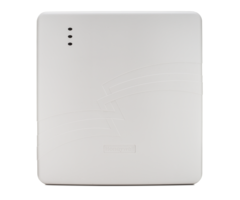
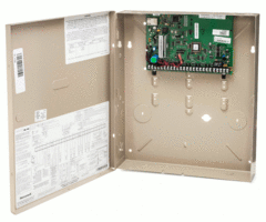
The Honeywell iGSMV4G is an external dual path communicator. Traditionally the VISTA-21iP would use the VISTA-GSM4G for cellular communications. However this GSM unit can only be used on systems with a sticker stating, "Supports VISTA-GSM4G." For those that do not have the sticker, the iGSMV4G is the only way to accomplish a dual path setup. First you will need to power down the panel and move the 'Internal IP/GSM jumper' to the off position (bottom two pins). The jumper is located just beneath the RJ-45 internet port on the board of the VISTA panel. After the jumper has been set to the off position you will need to connect the iGSMV4G. Check out the iGSMV4G installation guide which is great tool that walks you through the installation process step by step.
If this is a fresh installation follow these steps:
1. Test signal strength and determine location. (Install guide page 2-1)
Connect the unit's battery back up and AC power supply. Ideally the communicator can sit beside the panel so boot it up locally and check the LEDs for signal strength. You will need at least 3 LEDS for minimum signal to function. This is a rough test so if you have 3 or more just move to the next step. Your monitoring provider will be able to do more accurate testing once registered.
2. Mount the communicator. (Install guide page 2-2)
Simply mount the unit to the wall. This unit does not weigh very much so using zip-its or the included wall anchors will work well. Line up the back plate on the wall and trace the keyholes while the unit is level. Then pre-drill for the anchors. Make sure to use a bit that is slightly larger than the small end of the anchor. This way the anchor will slide in snug. After you push in the anchors, screw in the screws leaving space for the wall plate to sit on before tightening them all the way down. After you sit the back plate on the screws you can tighten the screws so the device is snug to the wall.
3A. Standard Install. Land power connections. (Install guide page 2-5.) Check out the VISTA-21iP install guide for a diagram of the panel on page 10-5.
Remove AC power and battery from panel. Power down completely.
Connect the included transformer to terminals 1 and 2 on the communicator. There is no polarity so just connect each terminal to its own connection on the transformer. Then plug into a 110 AC outlet.
Connect power to the alarm panel. Terminal 3 (ECP +) on the communicator goes to terminal 5 (AUX +) on the panel. Then connect terminal 4 (Ground) on communicator to terminal 4 (Ground) on the panel.
3B. Shared Transformer Install. Land power connections. (install guide page 2-9) Check out theVISTA-21iP install guide for a diagram of the panel on page 10-5.
Remove AC power and battery from panel. Power down completely.
Swap existing transformer with the iGSMV4G included transformer. Then wire terminals 1 and 2 on the communicator to terminals 1 and 2 on the panel. This will share the connections to the transformer that powers the panel.
Connect the iGSMV4G power terminals to the alarm panel. Terminal 3 (ECP +) on the communicator goes to terminal 5 (AUX +) on the panel. Then connect terminal 4 (Ground) on communicator to terminal 4 (Ground) on the panel.
4. Land data connections. (Install guide page 2-5)
Connect terminal 5 (data in) on the communicator to terminal 7 (data out) on the panel. Then wire terminal 6 (data out) on the communicator to terminal 6 (data in) on the panel. After the power and data connections are made, verify the connections and ensure there are no shorts across terminals.
5. Connect the included back up battery. (Install guide page 2-5)
Start off by placing the battery in the compartment in the lower right side of the back plate. Screw in the retainer clip to the backplate in order to secure the battery in place. Connect the red and black spade connectors to the same color on the battery terminals. Then, plug the battery connection into the J1 battery port found on the communicator's board.
6. Reboot the alarm panel.
Reconnect AC transformer to the wall outlet. Let the system fully reboot. If you get any faults try doing a disarm to clear any residual faults out of the memory. Keep in mind that you will get a tamper alert if the cover is off your communicator. If you are still testing you can leave it off. Just keep in mind that you will need replace the cover if you want to arm the system.
7. Program the iGSMV4G. (Install guide page 3-1)
Connect with a Honeywell dealer in order to activate and register the radio on the Alarmnet server. We offer no contract, month-to-month alarm monitoring that include cellular communication for an additional $10 per month. We will dial into your panel remotely using software that allows us to make the programming changes for you. Simply sign up for the plan you would like and send us the MAC and MAC CRC address from the iGSMV4g. This can be found on a sticker inside the module and on the box. Take a picture or jot it down so you can email it into your dealer.
For further information on the iGSMV4G, please check out our FAQ page where you can also find the quick install guide.
Did you find this answer useful?
We offer alarm monitoring as low as $10 / month
Click Here to Learn MoreRelated Products


Related Categories
- Answered
- Answered By
- Frank Longo
