Wiring a 5833H to a VISTA Security System
Related Products


Related Categories
- Small Business Security Systems
- Monitored Home Security Systems
- Home Security Systems
- DIY Wireless Security Systems
- DIY Wired Security Systems
- Business Security Systems
- Apartment Security Systems
Description
http://alrm.gd/get-monitored.
Transcript
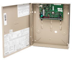
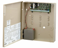
hi DIYs joy at alarm grid and today we're going to show you how to wire up a 50 883 transceiver module now the 58 83 is a standalone transceiver that can be used with a compatible Vista system and it lets you interface wireless devices to the system as you can see right here we have our vista 21ip all set up and on the board these don't have a receiver module to work with wireless devices now when I say wireless devices I'm talking about the 5800 wireless line there's a whole bunch of different sensors available if you go to our website we have a ton of them listed there's a many different types and you should be able to find one that suits the need that you're looking to secure with your system whether it be arming Berg fire flood detection all that it's all within the 5800 line so definitely check it out but as I said before on this system it doesn't have a built in receiver or transceiver module so you actually have to install one now I have a new 58 83 in the box right here and I just want to review what I mean by transceiver when I say it so there's two different types of receivers for the system there's receiver only modules and there's transceiver modules the receiver modules they only receive information from sensors those devices they won't be able to support two-way to a devices such as the 5828 keypad that sends information in two directions to use that you would need to use a transceiver module that has a receiver and a transmitter built right into the unit the 58 83 does have that and it's the recommended one to use if you're going to use a standalone receiver or transceiver for your system another benefit to the 58 83 is that it can support as many wireless zones as the system can handle so if you want to go fully wireless you can just fill your zone list up with as many as you like with this device so let's take it out of the box this is the box right here we open it up we have our transceiver unit we have two antennas that install onto the unit we also have some other stuff - we have our instruction manual that's going to show us how to set the dip switches on the unit and we also have a little packet of screws and the wire connection for the for the device so if we pop this open there's a couple things in here you have your wire harness this is a four wire connection and it's got a little mod clip right there that can plug right into the the board on the 58 83 if I open it up I'll show you what that looks like so as you can see if I can find it right there this connection right here is the connection for the mod plug this is going to plug in right here onto the board and then this can connect back to the ECP bus on your system that's these four terminals it's going to use the same ECP bus that you use for any other device such as a keypad or any other powered device that needs to parse data back and forth from the system with this if this is going to be installed somewhere further away from the system and you won't be able to reach back to the system with the included wire harness you can always splice additional wires onto this to extend it to get it back to your panel now also you'll see that in the kit it actually comes with panel mounting screws and panel mounting plastic pieces what you can do with this is you can actually mount this inside of a of a alarm box such as this one with the board taken out of the white housing and mount it inside these screws will allow you to do that the only thing that you're going to want to do is if you do mount this outside of its plastic housing inside of a metal box the terminals up here on the right hand side these are gonna have to connect to the ground or these are gonna have to ground to a grounding connection if it's mounted inside of a metal box the reason for that is it's going to reduce the amount of interference that this device gets and it will allow it to continue to work with the maximum amount of communication range that it can use with 5800 devices now these terminals right here these are actually where the antennas go so if you're going to mount it inside of a metal box use the left ones to ground and the right ones are actually where your antennas are going to sit what they do is they just slip right in to the to the opening right there and then you're going to take a screwdriver and tighten the setscrew down there's two antennas that come with this device and you're definitely going to want to install both of them or you're gonna see really poor signal range also you're going to notice right here in the middle of the board are the dip switches for configuring the the 58 83 now on a Vista 15 P on a 20 P and on a 21ip the device addresses and these panels already set up so what you want this to be set to is having all the dip switches being set off as far as one through four if you look at the manual right here this actually shows you exactly how you have to consider the switches and on a non poling loop panel as in a panel that doesn't use polling loops such as the 15 feet of the 20 P and the 21ip you want it to be set to the non addressed item right there for that to hit that that'll set the the receiver at a 0 0 address which will make it work with the panel and it also automatically set the transceiver portion of it to address 28 which is also a preset device address in your system now if you look dip switch number 5 is has to be set to OFF dip switch number 6 is to enable the the transmitter so if you are using bi-directional devices you will want to turn dip switch number 6 on if switch number 7 isn't used and dip switch number 8 is used for deleting RF keypads which we're not going to get into today now one thing to take note of on the dip switches themselves you're going to see that there's this weird plastic film that's on the top of them that's actually an electromagnetic protector so it doesn't get damaged from any static discharge when you go to move the dips way you're gonna notice that you're gonna have to dig into the plastic screen it's gonna get kind of crappy you're gonna tear it a little bit and it will get holes that's totally normal and feel free to just leave that static protector on there even if it's damaged and ripped up it's still going to work and provide some protection you'll also want to make sure that you do your power calculation when adding this to the system this device doesn't take too much power the 58 83 it only takes 80 milliamps of power so if you do have a whole bunch of stuff on your system you will want to do a power calculation just to make sure that it doesn't over draw and give you some weird operation but if you only have a keypad or two on your panel it's not going to draw that much power and you can just go ahead and install it so as you can see we've mounted the 58 83 on the wall and it's ready to go the mod cable that comes with the 58 83 it's only about this long so what I have to do is actually extend it to get it into the box now if we take the cover off the 58 83 you'll see the mod cable right here and there's five wires that are attached to it now this connects to the ECP bus on the Vista system which is color coded and that's going to tell you that the cable that you're not going to use is the blue one the red and the black those are going to go to our power and ground and then our yellow and our green are going to go to the data connections on the system this little mod cable it's great to you actually have to use it to power this up and this is a this is going to plug in that this little clip right here on the side you just want to make sure that your orientation is correct it has these little slots here on the front of it and they're gonna go against the board and these little grooves on the back of the bond clip slip it right in and as you can see it starts to power up and it begins working because I already have it wired down here now if we look at our panel this is our extension cable that I've spliced into the mod cable from the the 58 83 and this cable has the same color codes as the mod cable I've got a black a red a green and a yellow what I've done is literally just take the wire from here and splice it to the wire on the cable and as you can see they're going to the corresponding terminals the black is going to terminal number four the red is going to terminal number five the green is going to terminal number six the yellow is going to terminal number seven you have any problems with the operation of your 50 at 83 or it's not powering up the first thing you're going to want to do is double check that your wiring connections for it are good and complete and then it is plugged in you do have any questions about installing a 58 83 on your Vista system feel free to give us a call eight eight eight eight one eight seven seven two it you can also head over to the website alarmgrid comm or send us an e-mail to support alarmgrid comm with any questions that you have we hope you enjoyed the video if you want to see more feel free to subscribe and hit the notification button to get updated when we post future ones have a great day thanks for watching
- Uploaded


