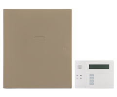
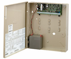
System Sensor RRS-MOD for 2-Wire i3™ Smokes on a VISTA-20P Panel
Related Products


Document Transcript
-
1
-
Step
-by-Step
Tech Support
Updated 10/6/11
Vista-20P / FA168C Family w/RRS-Mod & 2-
wire Smokes
When using the RRS
-Mod and the S
ystem
Sensor 2wta
-b smoke detectors, we have found that the pulsing
relay
(RRS
-Mod)
will cause multiple fire signals
to report to the central station
. To prevent this issue we have to program
the
fire zone differently
using a configurable zone type
rather than a zt of 09 or 16. See Below for the complete
programming changes with their explanations:
Definition:
Configurable Zone Type –
this is a zone type that you can create
to fit
your application. In our application we need
to prevent the multiple reports. W
e will create a Custom Zone type disabling Auto Restore
to
do
this.
Programming
our Configurable Zone Type:
The table below can be found on a worksheet defined in the installation instructions.
ENTRY 1
ENTRY 2
ENTRY 7
ENTRY 8
Response when system is disarmed and zone is:
Auto
Restore
Vent
Zone
Display Faults
Power Rest/
Verification
Use Entry
Delay
1/2
Use Exit
Delay
Respond as
Interior Type
Intact EOL
Open
Sho
rted
0 = Normal
0 = Normal
0 = Normal
0 = no
0 = no
0 = show alarms
when armed &
disarmed
0 = No
0 =No
0 = No
0 = No
1 = Alarm
4 = Alarm
1 = Alarm
1 = yes
1 = yes
4 = power
reset after fault
(by code +
OFF)
1 = Delay 1
4 = use
exit delay
8 =
Yes
2 = Trouble
8 = Trouble
2 = Trouble
2 = Delay 2
3 = Fault
12 = Fault
3 = Fault
1 = don't show
alarms when armed
(show alarms,
troubles, faults
when disarmed
3 = never show any
alarms, troubles,
faults
Entry 1 = 0
+ 8 =
8
Entry 2 = 1 + 0 + 0 =
1
12 =
verification
(see zone type
16)
ENTRY 3
ENTRY 4
Response when system is STAY and zone is:
Byp.
when
Byp.
when
Intact EOL
Open
Shorted
disarmed
armed
0 = Normal
0
= Normal
0 = Normal
0 = no
0 = no
Entry 7 = 0 + 4 =
4
Entry 8 = 0 + 0 + 0 =
0
1 = Alarm
4 = Alarm
1 = Alarm
1 = yes
1 = yes
2 = Trouble
8 = Trouble
2 = Trouble
3 = Fault
12 = Fault
3 = Fault
Entry 3 = 0 + 8 =
8
Entry 4 = 1 + 0 + 0 =
1
E
NTRY 9
E
NTRY
10
Alarm Sounds
Use Bell Time
out
Respond
as Fire
Zone
Trouble
Sounds
Chime when
Chime Mode
On
ENTRY 5
ENTRY 6
Response when system is AWAY and zone is:
Dial
Delay
Fault
Delay
0
= none
0 = No
0 = No
0 = None
0 = No
Intact EOL
Open
Shorted
1 = Steady Keypad
4 = Yes
8 = Yes
1 =
Periodic
beep
4 = Yes
0 = Normal
0 = Normal
0 = Normal
0 = no
0 = no
2 = Steady bell and
keypad
1 = Alarm
4 = Alarm
1 = Alarm
1 = yes
1 = yes
see fields *32,
*33
See ZT 0
9
2 =
Trouble
beeps
2 = Trouble
8 = Trouble
2 = Trouble
3 = pulsing bell and
keypad
3 = Fault
12 = Fault
3 = Fault
Entry
5 = 0 + 8 =
8
Entry
6 = 1 + 0 + 0 =
1
Entry 9 = 3 + 4 + 8 =
15
Entry 10 = 2 + 0 =
2
N
ow that we have defined the configurable zone type,
we need to program the panel. There are up to 4 configurable
zone types, 90, 91, 92, 93. We are going to add the final values to *182
(zone type 90)
. To enter the data
press:
*182 -
8 1 8 1 8 1 4 0 #15 2
W
e also w
ant
to program the panel to send the same report
code
as a ZT of 09
. This
is CID of 110 for an Alarm and
373 for a
T rouble (refer to the installation instructions for a list of CID codes). This is programmed in location
*183. To enter this press the following command: *183 -
110 373. -
2
-
Step
-by-Step
Tech Support
Updated 10/6/11
When programming zone
1
through the control panel you will enter a value of 90 for the zone type:
The
represents pressing the * (star) key
S
etting up through the compass software:
C
onfiguring the ZT:
U
sing Additional F
ire Zones:
I
f you have another fire zone, or are using Keypad Fire Panic, these also will trip the RRS
-MOD which is
wired to zone 1.
T
he pulsing RRS
-MOD,
without a latched smoke
detector
, will cause rapid Trouble/Restore reporting to
C.S.
When the RRS
-M
OD starts to pulse in conjunction with the bell output, the zone will report to the
panel a trouble on an open then a restore on close,
and will do this for the duration of the sounder. The
logic of the panel tells the dialer to report every T
rouble and e
very
Restore. This means
every time it
pulses it sends a signal to the dialer queue
, caus
ing
multiple
Trouble reports to be sent to C
entral
Station.
T
o prevent these repeat Trouble
reports when other Fire Zones are tripped, you
can
wire one of the trigge
rs
to the positive side of Zone 1
, and
program
the
trigger to activate upon “Alarm” of these other zones in
a
Z
one List. When one of these zones trip, the trigger will hold a short to ground on Z
one 1
, putting it into
Trouble
and preventing it from responding to the pulsing of the RRS
-MOD.
The different potentia
l
b
etween Zone 1 negative and Trigger negative causes trouble on the zone, not Alarm.
Enter Zn Num.
(00=Quit)
00
ZN ZT P RC IN: L
01 90 1 10 EL
01 Response Time
1
01 Report Code
1
st
01
2
nd
00
10
01 Partition
1
01 Zone Type
Config ZTYP1
90
ZN ZT P RC IN: L
01 09 1 10 EL
Enter Zn Num.
(00=Quit)
01 -
3
-
Step
-by-Step
Tech Support
Updated 10/6/11
See below for the wiring diagram.
The above schematic explains the wiring configuration. Now we have to program the panel to activate the trigger
17 (as shown above) when any zone exc
ept zone 1
is in
Fire
Alarm.
The Compass Screen Shots are found under the
Relay/X10 Tab.
*7
9 Programming:
Enter Output No.
00 = QUIT
00
17 Out Normal Low?
0=No, 1=Yes
0
Enter Output No.
00 = QUIT
17
Trigger 1 = Output # 17
Trigger
2 = Output # 18
DO NOT INSTALL HE
AT DETECTORS OR
PULL STATIONS ON THE SAME ZONE AS 2
-
WIRE SMOKES WHEN USING THE RRS
-MOD!
The
Jumper is ONLY to be used when you have
more than one Fire zone, including a keypad panic.
-
4
-
Step
-by-Step
Tech Support
Updated 10/6/11
*80 Programming:
*8
1 Programming:
If zone 1 is entered in this Zone List it will cause the LED of the Smokes on Zone 1 not to
Latch on Alarm!
01 Enter Zn Num.
(00 = Quit)
00
01 Enter Zn Num.
(00 = Quit)
95
01 Enter Zn Num.
(00 = Quit)
02
Zone list No.
(00 = Quit)
01
Output Funct. #
(00 = Quit)
00
Output Funct. #
(00 = Quit)
00
Output #?
17
01 Output Action
Off
0
02 Enter Zone Type
Disarming
22
02 Activated by:
Zone Type
2
02 A E P Trig
?00 0 0 -
ZL=1
Output Funct. #
(00 = Quit)
02
Output #?
17
01 Output Action
Stay Closed
02
Enter Event
Alarm
1
01 Zone List
01
01 Activated by:
Zone List
1
01 A E P Trig
?00 0 0 -
ZL=1
Output Funct. #
(00 = Quit)
01
- Uploaded


