What Field is Device Programming on a VISTA-21iP?
There is no single device programming field on the Vista-21iP. Because Vista-21iPs are addressable, everything connected to the keypad bus must have a unique address. Device addresses depend on device type and other factors, such as which zones are being used on an expansion module
In the chart below, you'll see a list of available ECP (keypad bus) addresses, and how each is enabled in panel programming. For example, if an RF Receiver is used, it must be set to address 00. The supervision zone for this is 100, meaning if the panel is told it has a receiver, it will supervise that connection, and if the connection is lost, it will display a check 100 on the keypad. The receiver is enabled by programming an entry in *24, or by programming any zone with an RF Input type (03, Supervised RF, 04 Unsupervised RF, or 05 Button RF).
TABLE OF DEVICE ADDRESSES
|
This Device |
Uses Address |
Reports as✝✝ |
Enabled By... |
|---|---|---|---|
|
RF Receiver |
00 |
100 |
*56 zone programming: input device type entry. *24 entry other than 00. |
|
AUI 1 (touchscreen) |
01 |
n/a |
Automatic if AUI enable field *189 enabled for AUI 1 |
|
AUI 2 (touchscreen) |
02 |
n/a |
Automatic if AUI enable field *189 enabled for AUI 2 |
|
AUI 3 (touchscreen) |
05 |
n/a |
Automatic if AUI enable field *189 enabled for AUI 3 |
|
AUI 4 (touchscreen) |
06 |
n/a |
Automatic if AUI enable field *189 enabled for AUI 4 |
|
Internal IP/GSM Device |
03 |
103 |
Automatic if installed and enabled in menu mode *29 |
|
Zone Expanders (4219/4229): Module 1 (for zones 09 - 16) Module 2 (for zones 17 - 24) Module 3 (for zones 25 - 32) Module 4 (for zones 33 - 40) Module 4 (for zones 41 - 48) |
07 08 09 10 11 |
107 108 109 110 111 |
*56 zone programming: Input device type entry then: Automatic if zone no. 9 - 16 entered as AW type or relay assigned Automatic if zone no. 17 - 24 entered as AW input type or relay assigned Automatic if zone no. 25 - 32 entered as AW input type or relay assigned Automatic if zone no. 33 - 40 entered as AW input type or relay assigned Automatic if zone no. 41 - 48 entered as AW input type or relay assigned |
|
Relay Modules (4204): Module 1 Module 2 Module 3 Module 4 |
12 13 14 15 |
112 113 114 115 |
*79 output device programming: device address prompt: Entered at device address prompt Entered at device address prompt Entered at device address prompt Entered at device address prompt |
|
Keypads: Keypad 1 Keypad 2 Keypad 3 Keypad 4 Keypad 5 Keypad 6 Keypad 7 Keypad 8 |
16 17 18 19 20 21 22 23 |
n/a n/a n/a n/a n/a n/a n/a n/a |
Data field programming is listed below: Always enabled, all sounds enabled Data field *190 Data field *191 Data field *192 Data field *193 Data field *194 Data field *195 Data field *196 |
|
RIS Communication |
25 |
n/a |
Automatic if Remote Interactive Services enabled in field *91 Panel Revision 3.13 enabled in *91 entry 2 (2) Panel Revision 4.21 or later, enabled by default, no user programming required |
It is important to note that ✝✝ addressable devices are identified by “1” plus the device address when reporting supervision issues. Enter a report code for zone 91 to enable supervision reporting (default = enabled). See field *199 for addressable devices (ECP) 3-digit or 2-digit keypad display options. 2-digit display will show as zone 91 for all devices. Keypads, including AUI devices, are not supervised.
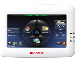
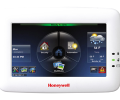
There are specific fields for enabling keypads, based on address. There are two types of keypad, AUI and traditional keypads. Traditional keypads are equipped with a number pad and display. AUI (Advanced User Interface) keypads, also known as Tuxedo Style touchscreens, use addresses 1, 2, 5 or 6 on the 21iP. Note that when using Total Connect 2.0, the app emulates an AUI keypad, and will use one of these 4 available addresses, or, by default, Address 2. These devices are enabled in programming location *189 as AUI 1, 2, 3, and 4, respectively. AUI 1 refers to Address 1, AUI 2 refers to Address 2, AUI 3 refers to Address 5, and AUI 4 refers to Address 6. AUI 1 and 2 are enabled by default for partition 1.
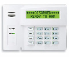
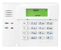
Traditional keypads use addresses 16 - 23 on the Vista-21iP. Each address, with the exception of 16, has its own programming location. Address 16 is always enabled on partition 1 with no sound suppression, and it can't be changed or disabled. Address 17 corresponds to programming location 190, address 18 corresponds to location 191, and so on. When enabling a keypad, the first entry in the field determines what partition the keypad will operate on, and the second entry determines if any sound suppression will be enabled. On keypads 17 - 23, you can suppress arm/disarm and entry/exit beeps, chime beeps, or both. This is useful if you have a keypad near a bedroom. In earlier panel versions, keypad addresses 17 - 23 had to be enabled through programming. Now, in version 4.21 or higher, all keypad addresses 16 - 23 are enabled by default on partition 1 with no suppression. Addresses 17 - 23 can still have sound suppression enabled, and the partition number changed in their respective programming fields.
Did you find this answer useful?
We offer alarm monitoring as low as $10 / month
Click Here to Learn MoreRelated Products

Related Categories
- Answered
- Answered By
- Julia Ross


