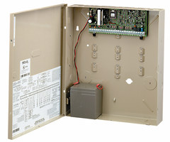
Where do I connect a Honeywell 4219 on a VISTA-20P?
While the Honeywell VISTA-20P supports up to (8) hardwired zones right out of the box, you can add a Honeywell 4219 hardwired zone expansion module to add additional hardwired zone capability. Each 4219 expansion module adds an additional (8) hardwired zones to your VISTA-20P. You can use multiple 4219 zone expanders to upgrade your Honeywell VISTA-20P to a maximum of (48) hardwired protections zones.
When installing the Honeywell 4219, you can use the 'TB2' terminal block or the (4) pin console plug found directly above the 'TB2' terminal block to wire the 4219 to your VISTA-20P alarm control panel. In fact, you can even use both the 'TB2' terminal block and the (4) pin console plug if you want a redundant connection. It does not matter which connection you decide to use, but it is important that you make the proper connection on the VISTA-20P alarm control panel. The first terminal on the 'TB2' terminal block and/or the first pin on the (4) console plug must be connected to terminal 7 on the VISTA-20P terminal strip. The second terminal on the 'TB2' terminal block and/or the second pin on the (4) console plug need to be connected to terminal 5 on the VISTA-20P. (You'll notice that the second pin on the (4) console plug is actually separated from the first pin by an empty slot.) The third terminal on the 'TB2' terminal block and/or the third pin on the (4) pin console plug should be connected to terminal 4 on the VISTA-20P terminal strip. Finally the fourth terminal on the 'TB2' terminal block and/or the fourth pin on the (4) pin console plug should be connected to terminal 6 on the VISTA-20P alarm control panel.
If you are using standard 4-conductor alarm wire with a red, black, green and yellow conductor, the following connections should be used. The yellow conductor should be connected between the 'DATA OUT' terminal (#7) on the VISTA-20P and terminal 1 and/or pin 1 on the 4219. The red conductor should be connected between the 'POWER (+)' terminal (#5) on the VISTA-20P and the second terminal and/or pin on the 4219. The black conductor should be connected between the 'GROUND (-)' terminal (#4) on the VISTA-20P and the third terminal and/or pin on the 4219. Finally, the yellow conductor should be connected between the 'DATA IN' terminal (#6) on the VISTA-20P and terminal 4 and/or pin 4 on the 4219 zone expansion module.
Did you find this answer useful?
We offer alarm monitoring as low as $10 / month
Click Here to Learn MoreRelated Products
Related Categories
- Answered


