Can I Add a High-Current, Wired Siren To An IQ 4 Hub?
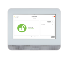
The Qolsys IQ4 Hub supports several siren options, depending on the panel version. A PowerG panel can support the DSC PG9WLSHW8 wired-to-wireless converter module, which also offers a wired siren output. Similarly, the Qolsys and Interlogix 319.5 MHz versions can support the Hardwire 16-F.

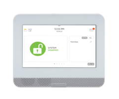
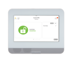
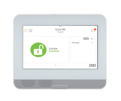
The Qolsys IQ4 Hub is a budget-friendly panel in the Qolsys IQ4 Series lineup. It has a few more features than the IQ4 NS, which has no touchscreen. And slightly fewer features than the IQ Panel 4. Each IQ4 Hub will support a single RF frequency. It comes in AT&T LTE or Verizon LTE cellular versions for users in the United States. In this recent blog post, we offered a table with a feature comparison between the IQ Panel 4, IQ4 Hub, and the IQ4 NS.
Because each IQ4 Hub only supports one RF frequency, it's important to note which panel you're using before you decide which of these siren setup options is right for you. If your panel supports PowerG sensors, then you can use the DSC PG9WLSHW8 wired-to-wireless module to add wired zones, PGM outputs, and even hardwired keypads, in addition to a wired siren.
The PG9WLSHW8 can support a siren, or sirens, with a current draw of up to 700mA. If the siren output requires more than 700mA of current, then a relay and a power supply will be required. The power supply should have its own backup battery and will require its own connection to AC power. An enclosure should be used to house this equipment and keep it safe from tampering.
Using a DSC PG9WLSHW8 to Add a Wired Siren:
The DSC PG9WLSHW8 (small enclosure) or the DSC PG9HRDW8 (large enclosure) wired-to-wireless converter can be used. Adding a siren using either of these modules is exactly like using a hardwired alarm panel to do the same. Either module provides up to 700 mA of current at 12 Volts DC, so they can power a pretty hefty siren straight out of the box. If more current is required, then you can also add a relay and a power supply, as shown further down.
Below are links to the IQ4 Hub versions that support PowerG:
- IQ4 Hub, AT&T LTE with PowerG Transceiver built-in
- IQ4 Hub, Verizon LTE with PowerG Transceiver built-in
Connect the Siren Directly to the Converter Module:

- Install the module. Using the Installation Instructions, install the PG9WLSHW8 or PG9HRDW8 as described. Be sure to make all wiring connections, including to the siren, prior to the initial power-up.
-
Connect the siren. As long as the siren being used draws 700 mA of current or less, connect it directly to the Bell + and Bell - terminals of the converter module.
- Connect the siren's negative wire or terminal to Bell - (negative) on the PG9WLSHW8 or PG9HRDW8, as shown above.
- Connect the siren's positive wire or terminal to Bell + (positive) on the converter module, as shown above.
- Connect the resistor. The bell output of the PG9WLSHW8 is supervised. It requires a 1,000Ω (1kΩ) resistor (color code: Brown Black Red) to be installed in parallel across the circuit. For proper supervision, this resistor should be installed in parallel at the last siren in the circuit. This means one side of the resistor connects to the siren's positive (+) wire or terminal, and the other side of the resistor connects to the siren's negative (-) wire or terminal.
-
Enroll the module. Once the wiring connections have been made, power the unit on by connecting the battery and then plugging in the power supply. Put the IQ4 Hub into Auto-enrollment mode by tapping the gray bar at the top of the main screen then tapping Settings > Advanced Settings > Enter Installer or Dealer Code (1111 or 2222 respectively, by default) > Installation > Devices > Security Sensors > Auto Learn Sensor.
Press the Enroll Button on the PCB of the converter module until the LED lights a solid orange, then release it. The panel should indicate that a sensor 460-xxxx is requesting to be added to your list (where 460-xxxx is the serial number of your converter module). Confirm that the proper serial number is displayed, then press "Yes". Be sure a Sensor Type of "Hardwire Translator" and a Sensor Group "13-Takeover" are selected. Complete the addition of the supervision zone. This is what allows the panel to supervise various aspects of the module, and also allows it to operate the siren wirelessly. - Test the module. For this FAQ, we want to specifically test the siren output of the converter module. Unfortunately, performing a siren test from the panel will not test the siren output of the PG9WLSHW8 or PG9HRDW8. Instead, you'll need to put your system on test with the monitoring station, if you have full monitoring, then cause an audible alarm to occur on the panel. You can do this by arming the system, and then faulting a burglary zone. Do not disarm the system, but instead allow an alarm to occur. Be sure the wired siren connected to the converter module is sounding.
Connect the Siren Using a Relay and Power Supply:

- Install the module. Install the DSC PG9WLSHW8 or DSC PG9HRDW8 as per the Installation Instructions. The basic installation of this module is the same in every scenario. Make all wiring connections, including those in Steps 2 and 3 below before powering the module on for the first time.
-
Connect the relay. When the bell output of the PG9WLSHW8 is energized, it will change the state of the RB5 relay. This completes the circuit to power the siren. Make the following wiring connections:
- Connect the Bell - (Negative) terminal from the DSC converter module to the NEG - (Power Negative) of the Altronix RB5.
- Connect the Bell + (Positive) terminal from the DSC converter module to the POS + (Power Positive) of the Altronix RB5.
- Connect the 1,000Ω (1kΩ) resistor across the RB5 NEG - (Negative) and RB5 POS + (Positive) terminals to supervise the wiring between the converter module and the relay module. With this resistor placement, if the wire between the relay and the module gets cut or is shorted, the system can provide you with a trouble indication. If you can't put the resistor across the terminals at the relay, you must at least wire it to Bell - (Negative) and Bell + (Positive) at the module itself, though wiring it this way will eliminate actual wiring supervision. Without the resistor, the bell circuit on the converter module will indicate a trouble condition to the IQ4 Hub.
-
Connect the Siren. The negative power connection for the siren is being controlled through the relay. Make the following connections:
- Connect the siren positive (+) wire or terminal to the power supply DC + (Positive) output.
- Connect the siren negative (-) wire or terminal to the NO (Normally Open) terminal of the relay module*
- Connect the DC - (Negative) output from the power supply to the C (Common) terminal of the relay.
-
Enroll the module. Enroll the PG9WLSHW8 or PG9HRDW8 with the IQ4 Hub as outlined in the panel's Install Guide. Put the IQ4 Hub into Auto-enrollment mode by tapping the gray bar at the top of the main screen then tapping Settings > Advanced Settings > Enter Installer or Dealer Code (1111 or 2222 respectively, by default) > Installation > Devices > Security Sensors > Auto Learn Sensor.
On the converter module, press the Enroll Button on the PCB until the LED lights solid orange, then release it. The panel should indicate that a sensor 460-xxxx is requesting to be added to your list (where 460-xxxx is the serial number of your converter module). Confirm that the proper serial number is displayed on the panel, then press "Yes". Be sure a Sensor Type of "Hardwire Translator" and a Sensor Group "13-Takeover" are selected. Complete the addition of the zone.
*These instructions assume the use of an Altronix RB5 which has continuity between Common (C) and Normally Closed (NC) when the relay is de-energized and has continuity between Common (C) and Normally Open (NO) when the relay is energized. If you use a different relay, check the specs and operation of that relay to determine its operation and proper wiring.
Using a Qolsys Hardwire 16-F to Add a Wired Siren:
Below are the IQ4 Hub versions that support 319.5 MHz sensors, including the Hardwire 16-F:
- IQ4 Hub, Verizon LTE with support for Qolsys, S-Line, and Interlogix 319.5 MHz sensors
- IQ4 Hub, AT&T LTE with support for Qolsys, S-Line, and Interlogix 319.5 MHz sensors
Powering the Siren via the Hardwire 16-F:
- Install the Hardwire 16-F. Follow the instructions provided with the Hardwire 16-F for proper installation and programming. Alarm Grid also offers an FAQ with detailed instructions for installation. Remember, this module will only work with an IQ4 Hub that supports 319.5 MHz sensors. Adding the Hardwire 16-F to a panel zone as a Hardwire Translator is what allows the panel to control the converter module's siren output, reset the 2-wire smoke zone if used, and supervise the tamper, input power, and backup battery.
-
Make siren connections. Connect the siren as described below:
- Connect the siren's negative wire or terminal to "GND" as shown in the diagram below.
- Connect the siren's positive wire or terminal to the terminal marked "OUT" as shown in the diagram below.
-
Connect the jumper wire.
- Connect a jumper wire from AUX OUT to SIREN IN on the Hardwire 16-F. This is where the power for the siren comes from.

If your siren will draw more than 500mA of current, then you can still use the siren output of the Hardwire 16-F, but you'll be using it to trigger a secondary relay, such as the Altronix RB5. The RB5 will then switch power on to the high-current siren(s). The power in this scenario is provided by an auxiliary power supply, which will require its own 1361-GT AC transformer and its own backup battery. This configuration should also be mounted inside its own enclosure next to the converter module to help prevent tampering.
The information provided below shows the use of a Resideo AD12612 power supply. It can provide up to 1.2 Amps of current for the siren. If more current is required, you can instead use an Altronix SMP3 power supply which can provide up to 2.5 Amps of current. When used with the 1361-GT transformer, it will provide up to 2.4 Amps of current.
Powering the Siren Using a Relay and Power Supply
- Install the module. The installation and programming of the Hardwire 16-F is exactly the same in this scenario as the one above. Follow the instructions for proper installation.
-
Connect the relay. Connect the RB5 or other third-party relay to the Hardwire 16-F. In this setup, you will connect to the same terminals that the siren would normally use. The relay you choose must activate when provided with approximately 12 Volts DC and must draw less than 500mA of current. It must also be able to handle the current load of the siren or sirens without becoming damaged. This is known as the relay's contact rating. The RB5 has a contact rating of 5A @ 220VAC or 28VDC and has a jumper setting that tells it to operate at 12VDC. It draws 120mA of current.
- Connect the NEG - power terminal of the relay to GND on the Hardwire 16-F.
- Connect the POS + power terminal of the relay to OUT on the Hardwire 16-F.
-
Wire the jumper. Again, in order to energize the RB5 or whatever relay you choose to use, you'll need the Hardwire 16-F siren output to provide the current required.
- Connect a wire jumper between the AUX OUT terminal on the Hardwire 16-F and the SIREN IN terminal.
-
Connect the siren. In the diagram shown above, we break the negative leg of siren power through the RB5 relay. This means that when the relay is de-energized, the siren is not connected to the negative side of its power supply and is therefore silent. When the relay is on or energized, it is connected, and is therefore sounding. The relay turns on when the Hardwire 16-F energizes its siren output.
- Connect the siren's negative terminal or wire to the relay Normally Open (NO) terminal.
- Connect a wire from the relay Common (C) to the DC power supply negative (DC-) terminal.
- Connect a wire from the DC power supply positive (DC+) terminal to the siren's positive terminal or wire.
- Set up power supply. The power supply shown in the diagram is an AD12612 from Resideo. It can provide up to 1.2 Amps of current at 12VDC when the 1361-GT or other transformer with the proper specs (16.5VAC, 40VA output) is used. Any DC power supply that provides the correct voltage and adequate current can be used here. Whatever power supply you choose, be sure it offers battery backup and that you supply a battery. Also, be sure to choose the correct transformer for your use case. The AD12612 can output either 6VDC or 12VDC, so be sure the jumper is set for 12VDC operation.

Important Notes: The Hardwire 16-F siren output is NOT activated by the panel's Siren Test. To test the siren users will need to cause an audible alarm. Also, the siren output is active whether the Hardwire 16-F has a battery connected or not. A low battery condition on the Hardwire 16-F will not affect whether or not the siren output activates.
For Those Who Don't Require a Wired-to-Wireless Converter:
You may be wondering what to do if you want a wired siren, but you don't need a wired-to-wireless converter module for any other reason. Or, perhaps you're using one of the panel versions that doesn't have a converter module that also supports a siren. You can check out this FAQ, which shows how to use a Z-Wave relay from ZooZ to control a high-current siren.
Did you find this answer useful?
We offer alarm monitoring as low as $10 / month
Click Here to Learn MoreRelated Products


- Answered
- Answered By
- Julia Ross


