Training Posts

Posted By

In order to reboot a router remotely using a VISTA P-Series Panel, you will manually activate an output, which will fault a zone. The zone fault will be programmed to activate a Z-Wave switch, which is powering the internet router or modem. A cellular connection is required to do this.

And there you have it, that's how you do it! Just kidding! We're going to cover exactly what you need to do. Alarm Grid had this scenario come up recently and thought it would make a good case study to cover.

First, we wrote an FAQ that covers how to manually control a programmable output through the keypad. But then we thought that putting the FAQ together with information outlining the exact problem that we resolved by using the manual output command might add some much-needed context and show how this command can really come in handy. This also outlines one of the reasons why a cellular communicator is so important to have as a backup to an internet connection!

Let me set the scene: The hero in our case study spends several months each year away from his primary residence. The system installed in this residence is a Honeywell VISTA-20P with a Honeywell Home Tuxedo installed, as well as an LTE dual-path communicator. The Honeywell LTE-IA or the Honeywell LTE-IV are equally suitable for use in this scenario. In addition, any of the compatible automation controllers, such as the Honeywell VAM or the older Tuxedo Touch WIFI, could be used instead of the newer Honeywell Home Tuxedo.

The Problem

While our hero is enjoying his time away, he discovers that his internet connection at home is down. Of course, if he were at home, the first thing he would do, after verifying that his ISP isn't experiencing an outage, is reboot his router to see if the connection comes back up. But he's not at home, and furthermore, there is no one he can send to his home to perform this task for him. Now, since he has a dual-path communicator with the cellular connection enabled and active, he doesn't have to worry that his panel won't be able to communicate a signal if the alarm goes off. He's safe in that regard. However, in addition to the alarm panel's ability to send signals through the internet when it is available, the Tuxedo also uses the internet to provide a communication path to Total Connect 2.0 so that he can control his Z-Wave automation devices remotely. This is a problem, and it's the problem we're here to solve.

Just to recap, we have a VISTA-20P Panel that is working, and it can communicate alarm signals via the cellular path. It can also be controlled via Total Connect 2.0 through the cellular path. We have a Honeywell Home Tuxedo that is working, and it can communicate with the panel through its hardwired keypad bus connection, but it can't communicate to TC2 through the internet. This means there is no way to remotely control Z-Wave Automation devices. Finally, we have an LTE dual-path communicator that is working on the cellular path, but not on the internet path.

The Solution

Basically, what this requires is a way to send a command from Total Connect 2.0 to the VISTA-20P Panel through the communicator's cellular connection. This command must be something that the panel can perform based on an entry from a keypad. In this case, we are going to enter a command via the TC2 keypad that will cause a programmable output to change state. This output is connected to a zone on the panel. When the output changes state, it will fault the zone. Then, based on the programming in a scene, the Tuxedo will turn the Z-Wave Module that is connected and providing power to the router OFF. This will drop power to the router. After a few seconds, another command will be entered through the keypad which will restore the zone, and a second scene will tell the Tuxedo that a restore on the zone causes the Z-Wave module to turn back ON. This will restore power to the router.

Here are the full details for this solution:

The first step in setting this up is making sure that you have an available zone to use as your triggering zone. If you have one of the hardwired zones on the panel available, then you can actually use Output 18, Trigger 2 for this purpose. Any of the hardwired zones 2 thru 8 can be used with this trigger. You can also use Output 17, Trigger 1, but it provides more current than Trigger 2, so we recommend that you save it for other potential uses. If you don't have one of these zones available, then you can use a zone on a Honeywell 4219 or 4229 8-zone expander, but this will also require the use of a relay instead of a trigger. If you are using the 4229, it has two (2) programmable relays built into it. If you are using the 4219, then you will need to add a Honeywell 4204. It is also possible to use a zone input from a wireless zone, such as a Honeywell 5816, along with one of the above mentioned relays.

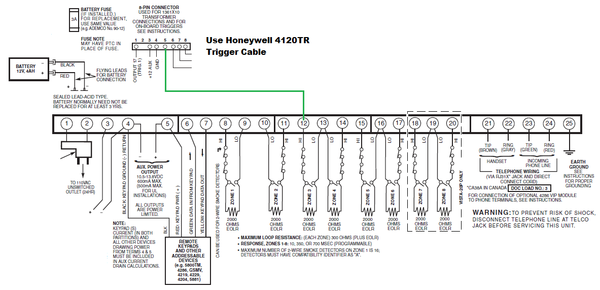
One reason we love using Trigger 2, Output 18 for this is because it's so simple. Output 18 is already enabled in panel programming location *79, and as long as its programming hasn't been changed from the default, no additional programming is required for the output to work. However, there is still the matter of programming the zone to be used. In our example, we show Output 18, Trigger 2 connected to Zone 03. As you can see in the diagram below, we have connected the trigger to the Hi side of the zone, on terminal 12. As mentioned before, you can use this configuration on any of the Zones 02 thru 08, connecting the trigger wire to the Hi side of the zone. The reason you can't use this on Zone 01 is because the Zone 01 negative is completely isolated from all other negative terminals on the board. In order for the trigger to work to fault the zone, it must be common to the zone negative when the trigger is activated.

If you need to use a relay instead of the trigger, you will need to wire the relay to the zone so that when you turn the Relay ON, it faults the connected zone, and when you turn the Relay OFF, it restores that zone. The way this must be done will depend on the type of zone it is being connected to. When using a 5816 with the input terminals, you will need to wire one terminal of the transmitter to the relay's Common (C) and the other terminal to the relay's Normally Closed (NC). If you're using an expansion zone on a Honeywell 4219 or Honeywell 4229, then the wiring used for this zone, and whether or not an End-of-Line Resistor (EOLR) is used, will depend on how the rest of the zones on that expander are configured, as well as on the age of the expander. Earlier versions required an EOLR for each zone, while newer versions provide an option not to use the EOLR, based on the setting of a dip switch. The important thing to know here is that when a 4204 or 4229 relay is OFF, it has continuity between Common (C) and Normally Closed (NC). When it is ON, it has continuity between Common (C) and Normally Open (NO).


With the output wiring out of the way, we can move on to programming the zone. We're not going to go through the entire zone programming process. You can find information about how to program a zone on a VISTA-20P Panel in this FAQ. The two important things to know when it comes to zone programming are the Zone Type and the Hardwire Type. The Zone Type should be set to Zone Type 23, No Alarm Response. This Zone Type was specifically created to allow the panel to activate outputs based on a zone's change of state. Basically, Zone Type 23 allows the panel to recognize that a fault and/or fault restore has occurred on a zone, without it having to display a fault for that zone, or take any other action with regard to the zone itself. Zone Type 23 will never show a fault, and it will never cause an alarm condition. The Hardwire Type should be set to Normally Open (Entry 2 when prompted). Again, see the FAQ linked above for full details on zone programming. The Hardwire Type programming of Normally Open is specifically meant for use with the trigger connection shown above. If using a relay instead of a trigger, the Hardwire Type or Input Type setting may need to be different, depending on your wiring configuration, and the zone number.

The next step is to pair the Z-Wave module with the Honeywell Home Tuxedo. As always, we recommend that you first Exclude or Remove the Z-Wave device using the Tuxedo, before attempting to Include or Add the device. The reason we always recommend doing this is because devices are often joined to a Z-Wave network at the factory as part of Quality Assurance (QA). In many cases, once the device has been successfully joined to the test network, it is never cleared, and is simply packaged and sold as it is. Once a Z-Wave device has been paired with a network, it holds onto that network information until it receives a command telling it to forget the old network so that it can join a new one. The process of Excluding or Removing, is what tells a Z-Wave device to forget the old network. It's fortunate that any Z-Wave controller can tell any Z-Wave device to forget its old network!

A word about which Z-Wave module to use. You can use either an in-wall switch, or a plug-in module. If your Z-Wave Automation Controller supports Z-Wave Plus, then we always recommend using a Z-Wave Plus device. Although any Z-Wave controller can support just about any Z-Wave module, a Z-Wave Plus module loses its Z-Wave Plus attributes, including extended range and battery life, when used with an older Z-Wave controller. We like the idea of using a plug-in module, as it allows you to easily move your router if you begin to have range or interference issues.

Once the Z-Wave module has been learned into the Tuxedo, VAM, or Tuxedo Touch WIFI you then need to create a scene which will tell the module to turn OFF when Zone 3 (or whatever zone you choose to use) is faulted. You will need to program a second scene to tell the same module to turn ON when Zone 3 is restored. The easiest way to perform this programming is through Total Connect 2.0. We like to program scenes using the website, the examples that follow will assume that is how the scenes are being setup.

After logging into Total Connect 2.0, choose the menu option for scenes. If you do not see this option, contact your alarm dealer, and be sure that your account is properly configured, and that your monitoring plan includes access to Automation. For Alarm Grid customers, this would be our Silver Plan (Self or Full), or higher. After clicking on Scenes, choose Create Scene.
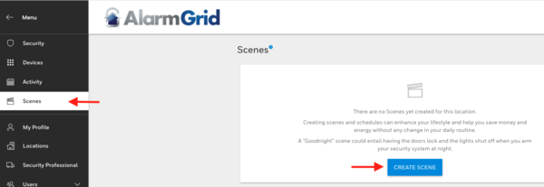

This will take you through a scene creation wizard. The first step is to name the Scene. This should be something easy to distinguish from other scenes, such as "Router Off". After choosing Continue, you will see where you can choose how the scene will be triggered. In our case, we want Triggered by a device, and when we expand this option, we then want to expand the section titled Sensors. Under Sensors, we see Zone 3, which we have named Router. When we expand this option, we can choose that this scene will activate when Zone 3 is Open (faulted) or Closed (restored). We intend to turn OFF the Z-Wave device when Zone 3 is faulted, so we will choose "When it is open".
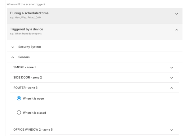

After choosing which zone(s) you want to trigger the Z-Wave device, you will be taken to Step 3 of the scene creation wizard. In this step, you will choose which device (or devices) you want to control, and whether you want them to turn ON or OFF. This is our Router OFF scene, so we set our action accordingly.

Now that we have created an initial scene, in order to add the second scene (the one that will turn the router power back on) we need to click the + symbol in the upper right of the Scenes screen.


The programming for this scene will be almost identical to the first scene. We still want to trigger by device. The device is Sensor 3, which we named ROUTER, and we want the Z-Wave device to be turned ON when Sensor 3 is Closed, meaning the fault on the zone is restored. Here's the summary for the second scene.
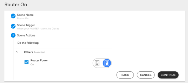

That is the end of the programming and wiring for this solution. The final step is for our hero to manually activate Trigger 2, Output 18 through the keypad screen in Total Connect 2.0. Do this by entering the following command:

4-Digit Code + [#] + [7] + [18]

By entering this command, we're telling Output 18, Trigger 2 to activate. When it activates, it connects to ground. This ground is common to the Lo side of Zone 3. This causes a short on the zone (which is why we programmed it as Normally Open), which in turn causes it to fault. The fault on Zone 3 causes the Z-Wave device being used to power the router to turn OFF, powering the router down.

After around 20 seconds, our hero should enter the following command to restore Zone 3:

4-Digit Code + [#] + [8] + [18]

By entering this command, we are telling Output 18, Trigger 2 to deactivate. When it deactivates, the trigger disconnects from ground. This opens the circuit on Zone 3, causing it to restore from a faulted condition. This in turn causes the Z-Wave device being used to power the router to turn it back ON, powering the router back up. Once more, keep in mind that this option is only available because the customer in question, our hero, chose to use a dual-path communication method. If he had chosen to use an IP only connection, there would be no way for him to initiate the keypad command through Total Connect 2.0 that gets this ball rolling.

If you happen to be using a relay instead of the trigger output, there will be a few minor tweaks that you will need to make to this process. One of those tweaks will be the output number that you will use when performing this command. The FAQ that we linked in the second paragraph above goes into more detail on how to set this up using a relay, including covering the programming required in programming location *79.

If you need further assistance using this setup with a relay, feel free to reach out to us at support@alarmgrid.com. Our technical support staff are available M - F from 9:00 am to 8:00 pm Eastern. We will have some closures soon due to the holidays, so pay attention to our blog for information about when those will be. As always, we look forward to hearing from you!

Tags: , , ,

Comments


Posted By

You have likely heard us talking about the benefits of PowerG Sensors at one point or another. Today, we figured we would break down the benefits of these sensors and explain why we like them so much. Let's take an in-depth look at PowerG Sensors and all of their wonderful benefits.


PowerG Sensors were originally designed for the hardwired DSC PowerSeries NEO Systems. By adding a compatible transceiver unit to your PowerSeries NEO, the system will be able to support PowerG Sensors. Johnson Controls, which you may know as the parent company of DSC, took the technology associated with PowerG Sensors, and brought it over to the Qolsys IQ Panel 2 System. This move was not a major surprise, as Johnson Controls also had partial ownership over Qolsys at the time, and Johnson Controls has since bought out Qolsys entirely.

The addition of PowerG support for the IQ2 marked the beginning of the Qolsys IQ Panel 2 Plus, which is how the system is still marketed and sold today. PowerG support is also available for the DSC Iotega, though that panel has largely flopped due to its lack of local end user programming. Today, the Qolsys IQ Panel 2 Plus represents the most popular panel for supporting PowerG. All versions and variants of the IQ Panel 2 Plus support PowerG Sensors, and their exceptional performance makes them the go-to choice for IQ2+ users who want equipment with the best versatility and protection.

Starting with the range, PowerG Sensors can be used from up to 2,000 feet away from the IQ Panel 2 Plus when they are used in an open air environment. By open air environment, we are talking about a perfect setting with a direct line of sight, and no obstacles between the sensor and the alarm panel. Most homes and businesses do not provide the ideal, "open air" environment, as there are usually walls and metal appliances present. When you see us mention that 2,000 feet open air range, take that with a grain of salt, because in practice, the range is likely a bit less. But still, we can undoubtedly say that PowerG offers arguably the best wireless range in the security industry. Even if its nominal range isn't quite as far as its "open air range", it is still a very powerful signal that can help you overcome the range issues that other sensor lineups may experience. It is great for use in detached garages, barns, multi-building complexes, and even just large industrial buildings.


To make matters even better, there is also a PowerG Repeater, the PG9920. This device will effectively double the range of any PowerG Sensor and help you overcome range limitations caused by thick walls and other obstacles or signal disruptions. The repeater works by taking the signal sent out from any PowerG Sensor and sending it out a second time with just as much power and force as when it was first sent from the original sensor. By strategically placing the repeater, it's theoretically possible to double the useful wireless range of these sensors. That would mean that they can be used from up to 4,000 feet away from the IQ2+ in an open air environment. And if your building is particularly large, you may even have repeaters going away from the IQ Panel 2 Plus System in different directions, including up and down in building stories above or below.

But PowerG Sensors offer more than just an impressive wireless range. They are also known for their exceptional security. This is thanks to their military grade 128-bit AES encryption. To put this as simply as possible, the PowerG Sensor and the panel share a unique encryption key at the time of pairing. The sensor must provide this encryption key to the panel whenever it transmits a signal. Additionally, the panel must then provide a return response with the encryption key as verification in order for the command to go through. In the past, we have referred to this two-way communication process as a "digital handshake". Because of this encrypted pairing process, a PowerG Sensor actively knows whether or not it is currently paired with a panel. You may need to factory default a PowerG Sensor before you can pair it with a new system.


PowerG Sensors also take proactive measures against RF jamming. When a wireless sensor communicates with an alarm panel, it does so at a certain wireless radio frequency (RF). When we talk about RF jamming, we are referring to any malicious technique that prevents wireless signals from reaching their intended destination. This is accomplished by blocking the receiver with a stronger signal at the same wireless frequency as the device that is legitimately trying to communicate with it. When this is done on an alarm system, the system doesn't receive the incoming signals from faulted sensors, and no action is taken during a security breach or an unfavorable environmental condition. Early wireless sensors did not take this into account, and this made RF jamming an effective way to defeat an older wireless system.

The way that PowerG Sensors overcome RF jamming techniques is through a process called Frequency Hopping Spread Spectrum (FHSS). This process involves splitting the RF bandwidth into multiple channels. Each independent channel represents a unique radio frequency for wireless communication to occur. The transmitter (the PowerG Sensor) and the receiver (the alarm panel) both agree on a set of channel hopping sequences that will take place. These sequences are encrypted and time-based for them to occur seamlessly. Since the transmitter and the receiver are both synchronized, they can switch between channels very rapidly. A potential intruder would never be able to re-tun an RF jamming device to keep up. In the case of the PowerG Sensors, the frequency hops occur between 912 MHz and 918 MHz. There are 50 different unique frequency channels that are used, and frequency switches occur 64 times per second. More information on FHSS is available here.

One other benefit of PowerG Sensors that we have never discussed previously is their Adaptive Transmission feature that helps them conserve battery life. This is why you will often see a PowerG Sensor with a very long expected battery life, sometimes more than ten (10) years). Adaptive Transmission involves two-way communication between the PowerG Sensor and the alarm panel. The alarm panel will tell the PowerG Sensor how well its signal is being received. The PowerG Sensor can then adapt its outgoing signal so that it reliably reaches the panel, without expending too much energy. The sensor and the panel regularly exchange this information so that the ideal amount of energy is always used in signal transmissions. This saves battery life in the long run.

We have also found that PowerG Sensors are extremely easy to enroll and they offer the reliable and effective performance that you should expect out of your security system. We wholeheartedly recommend them for use on the Qolsys IQ Panel 2 Plus, as well as any other compatible alarm system. It is expected that the upcoming Qolsys IQ Hub will also be able to utilize PowerG Sensors, so look forward to using PowerG Sensors on that panel once it is available.


For now, if you have any questions about PowerG Sensors or the systems that support them, or if you are interested in signing up for new alarm monitoring service, then please reach out to us by emailing support@alarmgrid.com. We'll be available to check your emails from 9am to 8pm ET M-F. We look forward to hearing from you!

Tags: , , , , , , , , , , , , , , , , , , , , , , , , , , , , , , , , , , , , , , , , , , , , , , , , , , , , , , , , , , , , , ,

Comments


Posted By

It's that time of the week for a video recap! We have been busy getting started with our holiday buying guides, so we haven't had quite as much time for new videos. But we still managed to put up a few new ones for you to check out. Let's take a quick look at the newest Alarm Grid videos!

Time Needed to Activate My Alarm Grid System

I provide you with an estimate for the amount of time it will take to activate your new security system for alarm monitoring service. Our activation slots are scheduled for one hour in length, and the typical activation is completed in around 30 minutes. You can help us make your activation go smoothly by having your system installed with sensors programmed, being on-site and ready to work with your system, knowing the important system codes beforehand, and listening carefully to your activator.

Number of Zones On a Wireless System Cannot be Increased

I explain how the number of available zones on a wireless alarm panel cannot be increased. A wireless system has built-in logic, and the number of zones it can support is based on its internal firmware. There is no way to increase this limit, and once you run out of zones, you would need to get an entirely new system to add more. The good news with wireless systems is that all system zones are usually readily accessible right out of the box, with no extra hardware being needed. You just need to get compatible wireless sensors.

Honeywell Lyric System & Garage Door Control

Jarrett explains how the Honeywell Lyric can be set up for garage door control. To do this, you must get a Honeywell 5877 Relay. This unit will wire into your compatible garage door controller. Remember that MyQ Garage Door Controllers are not compatible. You can enroll the 5877 with your Lyric, and then the Lyric will communicate with the 5877 to control the garage door. You must also get a Honeywell 5822T to monitor the Open/Close status of the garage door. This setup will also allow for garage door control through Total Connect 2.0.

Activating a System for Monitoring with Alarm Grid

Jarrett discusses the importance of activating a security system for alarm monitoring service. The user will need to choose an alarm monitoring plan for their system. This will determine how the system communicates (IP, cellular, or both), whether the user has coverage from a central station, and what remote functions will be available for the user through an interactive platform like Total Connect 2.0 or Alarm.com. Activating a system for central station service is the only way to get a certificate of alarm (CoA) for an insurance discount.

Tags: , , , ,

Comments


Posted By

Alarm Grid is here again with its latest video recap! We have a lot of videos featuring touchscreen keypads this week, though some other topics are covered as well. As usual, Jorge, Jarrett, and yours truly are all represented. Let's check out the latest Alarm Grid videos from the team!

Pairing a 2GIG SP2 with the 2GIG GC3e

Jarrett helps you pair a 2GIG SP2 Keypad with a 2GIG GC3e Security System. Adding the SP2 Keypad will provide you with a secondary on-site location for controlling your GC3e System. You might consider installing it by your front door, by your garage door, by your back door, or in your master bedroom. Remember that the SP2 is for security functions only, and it cannot perform automation commands. The wireless keypad pairs with the GC3e through WIFI or by using an Access Point (AP).


How to Tell If a Keypad Has an RF Receiver Built-In

Jorge explains how you can determine if your alarm system keypad has a built-in RF receiver. It can be easy to confuse a keypad like the Honeywell 6160RF, which has an integrated receiver, with a similar-looking keypad that does not, such as the Honeywell 6160. If you have a hardwired alarm system, then the benefit of adding a wireless receiver is that you will be able to begin pairing compatible wireless sensors with the system. And if your keypad has a built-in receiver, then you won't need to add a standalone receiver unit.


Remove a PG9914 From its Mounting Bracket

Jarrett shows you how to remove a DSC PG9914 PowerG Motion Detection Sensor from its mounting bracket. Like all motion sensors, properly positioning and mounting the PG9914 is very important for achieving the results you want. If it is positioned improperly, then it may cause false alarms, or it may not activate when movement is present in the area. Proper mounting is also crucial if you intend to use the motion sensor for pet immunity. The PG9914 supports pet immunity of up to 85 pounds.


Determining if Your Keypad is Alphanumeric

Jorge explains the difference between an Alphanumeric Keypad like the Honeywell 6160 and a Fixed English Keypad like the Honeywell 6150. Both keypad types are good for arming and disarming and bypassing sensors. But only an Alphanumeric Keypad is good for menu-driven programming. This is because an Alphanumeric Keypad will display the relevant information as you move through the menus. If you try to program on a Fixed English Keypad, you will basically be operating blindly.


Checking the ECP and RIS Address on the Tuxedo Touch

Jorge teaches you how to check the ECP Address and the RIS Address for a Honeywell Tuxedo Touch Keypad. These settings are important when you go to set up the Tuxedo Touch with a Honeywell VISTA Security System and Total Connect 2.0. The ECP Address is used for setting up the Tuxedo Touch as a keypad controller on the VISTA System, and the RIS Address is used for setting up the Tuxedo Touch as an automation controller on Total Connect 2.0.


Disarming Using the Tuxedo Touch Keypad

Jorge shows you how to disarm your Honeywell VISTA Alarm System by using a connected Honeywell Tuxedo Touch Keypad. Since the Tuxedo Touch is a wired touchscreen keypad controller for the system, it needs to be able to perform all the standard security functions. These include arming and disarming the system. When you are disarming, you are taking the system out of a secured state so that burglary/intrusion zones are unable to cause alarms on the system.

Bypassing Zones Using a Honeywell Tuxedo Touch Keypad

Jorge explains how to bypass zones using a Honeywell Tuxedo Touch Keypad. When the zone associated with a sensor is bypassed, that sensor is ignored by the system. In other words, the system will not provide any response if that sensor is faulted. You must bypass or restore any faulted zones prior to arming the system. Bypassing is often preferred over deleting a zone entirely, as you do not have to reprogram a zone after bypassing. You can just unbypass the zone later on and use it as normal.


Providing AC Power to an Alarm System

I explain how AC power is provided to an alarm system. AC power comes from a plug-in transformer that connects to an alarm panel using wire. The transformer takes the high-voltage power provided from the outlet, and it transforms it into low-voltage power that is suitable for powering a security system. The power travels down the wire and reaches the panel. This represents the primary power source for an alarm system. If AC power is lost, then a backup battery can keep the system running temporarily until AC power is restored.

Tags: , , , , , , , ,

Comments


Posted By

Alarm Grid is here with a video recap as usual! We only have a few videos this time around, and all feature yours truly. But don't worry, as we have some more videos featuring Jorge and Jarrett on the way soon. But for now we hope you enjoy these videos from October 28th. Let's take a look!


Duress Code Function On the 2GIG GC2e

I explain how the duress code works on the 2GIG GC2e Security System. The duress code feature is useful if you have a system that is monitored with central station service. When you enter the duress code, a secret alert is sent to the central station to indicate that you need help right away. Nothing appears on the GC2e Panel, so it's a great way to discreetly request immediate assistance. The duress code is hard-coded to user slot 8 on the GC2e.


Different Alarm Types On Security Systems

I explain how there are different types of alarms on security systems. The alarm types that can occur on a security system include burglary/intrusion alarms, police panic alarms, life-safety alarms, and auxiliary alarms. The response provided by a central station operator will depend on what type of alarm occurs on the system. For example, a very different response is warranted for a life-safety alarm like a fire alarm or CO alarm, than what is needed for a burglary/intrusion alarm.


How an Alarm System Backup Battery Works

I explain the purpose and function of a backup battery on a security system. The backup battery keeps the system running when AC power is lost due to an electrical outage or the plug-in transformer being disconnected. The battery slowly stores power while the system is running on AC power. That way, it is ready to activate as soon as primary power is lost. Batteries vary in terms of how long they can keep a system running. Some batteries can maintain alarm system power on their own for at least 24 hours.

Tags: , , , , , , , , , , , , , , ,

Comments


Posted By

It's time for our weekly video recap! And this might be our biggest one yet! We have a few videos back from the 16th that didn't make it into the last recap, as well a bunch of new videos from last week. We have videos featuring Jorge, Jarrett, and myself. Let's check out the videos!

Properly Replacing a Bad Sensor On a 2GIG GC3 or GC3e

Jarrett demonstrates the correct process for replacing a bad sensor on a 2GIG GC3 or 2GIG GC3e. The steps to follow for replacing a bad sensor on the GC3 or GC3e include clearing out the zone and then reprogramming it from scratch. Simply deleting the Serial Number (SN) and providing the new one can result in a "bypassed at device" error message. This will result in the sensor not working correctly. Other unusual system behavior may also occur.


Alarm.com Limits for Z Wave Devices

I explain the Alarm.com limit for the number of Z-Wave devices per account. Up to 122 devices from the panel will be pushed over to the Alarm.com platform for remote access and control. All Z-Wave devices numbered 123 and beyond will only be available at the panel for local operation. You can delete older Z-Wave devices that are still paired with Alarm.com to make room for new ones. You should pair the 122 devices that you want to use remotely first, allow Alarm.com to sync, and then add additional sensors for local control only last.


Clip Limits With Alarm.com Video Service

I explain the clip limits for Alarm.com Video Service. In order to get true video surveillance with Alarm Grid, you must have either a Platinum Level Plan (Self or Full) or a Video-Only Plan. At the base level, a true video plan will offer support for 1,000 monthly and total clips, as well as four (4) cameras and an SVR device. But by upgrading to Video Analytics, your monthly and total clip limits will both increase from 1,000 monthly and total clips to 3,000 clips of both types.


Changing the SiXCOMBO Batteries

I show you how to replace the batteries for the Honeywell SiXCOMBO. This wireless sensor uses four (4) lithium CR123A batteries for power. Its expected battery life is about five (5) years. You must open up the SiXCOMBO by twisting the sensor counterclockwise against its back plate. When closing the sensor, make to align it properly, and twist clockwise to secure. You get a low battery message on the panel to let you know when replacements are needed.


Self-Monitoring a Honeywell L3000

I explain how you can self-monitor a Honeywell L3000 System. Self-monitoring means that the system is not connected with a central station, and all system alerts are sent to the end user via text and/or email. For an L3000, this is possible using the Total Connect 2.0 service from Resideo. You will need a compatible AlarmNet Communicator for the L3000 System to make this possible. Both the Honeywell LTE-L3A and the Honeywell LTE-L3V work great for this job when used with the L3000.


Enrolling a PowerG Wireless Sensor to an Alarm Panel

Jorge shows you how to enroll a PowerG Sensor with a compatible alarm panel. PowerG Sensors are wireless devices that offer a fantastic signal range and 128-bit AES encryption. Compatible systems for PowerG Sensors include all versions of the Qolsys IQ Panel 2 Plus, the DSC Iotega, and any DSC PowerSeries NEO System with an added PowerG Module. Most PowerG devices can transmit a signal for auto-enrollment by either powering on or by pressing and holding a device enrollment button until its LED light turns solid orange.


Connecting the 2GIG GC3e to WIFI

Jarrett shows you how to connect the 2GIG GC3e to a local WIFI network. The 2GIG GC3e System will use its WIFI connection to communicate with Alarm.com. However, Alarm.com requirements mandate that the system also has an active cellular communication path set up. This will require an added cellular communicator. The WIFI connection will just work as an additional pathway for facilitating communication between the GC3e and Alarm.com. Remember that you will need the WIFI network password to complete the connection.


Checking Zone Faults on a Tuxedo Touch Keypad

Jorge shows you how to check for faulted system zones using a Honeywell Tuxedo Touch Keypad. A faulted zone refers to a programmed sensor that is in a non-restored or "active" state. A common example is a contact sensor in a faulted state due to a door or window being left open. The Tuxedo will display a message at the top of its main screen to indicate when there is at least one faulted zone. You must bypass or restore faulted zones before the system can be armed.


Scenes From Alarm.com Won't Be Pushed to GC3 or GC3e

I explain how when you build a smart scene in Alarm.com, that scene will not be pushed down to a 2GIG GC3 or GC3e Panel for local operation. Instead the scene will only be available for remote access through the Alarm.com website or mobile app. Likewise if you build a scene on the GC3 or GC3e, then it will not be pushed over to Alarm.com. You can include various smart home devices with scenes, including programmed lights, locks, thermostats, and more.


Checking the Firmware Version on a Tuxedo Touch

Jorge shows you how to check the firmware version for a Honeywell Tuxedo Touch Keypad. The Honeywell Tuxedo Touch is both a touchscreen keypad for a Honeywell VISTA System and a Z-Wave automation controller. Firmware updates for the Tuxedo may be periodically released to provide new features and improve device performance. The Tuxedo Touch receives firmware updates from an SD card slot. You must download the update to the SD card and then apply it to the Tuxedo Touch.


Getting Into the Z Wave Programming Section of a Tuxedo Touch Keypad

Jorge explains how to access Z-Wave programming for the Tuxedo Touch. Z-Wave functionality is one of the key features for this wired touchscreen keypad. You must access the Z-Wave Programming Menu for the Tuxedo Touch to begin enrolling Z-Wave smart home devices. It is advised that you clear any Z-Wave device from the network before attempting to enroll it with the Tuxedo. This is true even if the device is brand-new and you have never paired it with a Z-Wave network before.


Converting a Wired Alarm Into Wireless

I explain how you can convert a wired alarm system into a wireless alarm system by using a wired to wireless converter module. With a wired to wireless converter, you can take your existing hardwired sensors and use them with your new wireless security system as wireless devices. This can save you money by not having to purchasing as many wireless sensors. When choosing a wired to wireless converter, you must make sure that the module communicates at a wireless frequency that is compatible with your new wireless system.

Tags: , , , , , ,

Comments


Posted By

Last week, I made a post outlining the alarm registration policy in Pompano Beach, FL. In the post, I referred to a welcome letter that mentions the most common causes of false security system alarms. Today, I want to discuss one listed reason, which is having others use your alarm system.


Anyone who uses a security system should know how to use it responsibly so that false alarms do not occur. This includes users who are not the primary operators of the system. When you have another party operate your system, you are depending on them to not make any mistakes that could lead to a false alarm. Remember, false alarms waste the resources and time of the local authorities, and they can result in fines and penalties that you are held responsible for.

If you ever hire a person who will need to access the premises while you are away and disarm the system, then it is crucial that you do your part and make sure that they know how to use the system properly for basic disarming. This practice can apply to virtually any type of hired hand or assistant, including a maid, a babysitter, a maintenance person, or even a friend who is simply checking on your house while you are on vacation. It may be a good idea to invite them over and show them how to arm and disarm the panel.

Many users will have reservations about leaving a system code with an individual who shouldn't have access to the home all the time. System manufacturers are aware of this concern, and they have implemented a solution. A guest code, which is also sometimes referred to as a babysitter code, is a code that only works when the system is armed with that code. You can give this code to the person who needs to access your home while you are away so that it works during that particular instance, but not on other occasions.

There are some things to keep in mind if you decide to use a guest code with your system. As we mentioned before, the code will only work if it is used to arm the system in the first place. You must remember to use that code to arm on any given day where you are planning to make your home accessible to the other individual. This can be easy to forget in the hustle and bustle of the morning when you are scrambling to get out the door. You might slip up and accidentally arm using your normal code. It can also be a problem if you quick-arm the system without using a code. When quick-arming or single-button arming is used, it is as if the arming was performed by the Master Code. One practice that we have found useful is to leave a sticky note on the panel with the phrase "GUEST CODE". That way, when you arm before leaving, you will know to use the guest code. Obviously, you shouldn't write the actual guest code on the sticky note. But just the message alone will remind you which code to arm with.

The fact that a guest code will only work when it was used to arm the system is a bit of a double-edged sword. If you find out in the middle of the day that you need the other person to access your home, perhaps due to an emergency, and you armed earlier using a different code, then the guest code will not be of any help. A decent work around in that situation is to just disarm using an interactive monitoring platform like Total Connect 2.0 or Alarm.com. But it can admittedly be a bit cumbersome to require the other person to contact you and wait for you to open the app on your phone and disarm the system. Still, this is a pretty decent option for a system without any other easy solution. You can also rely on an interactive platform entirely and skip out completely on using a guest code. But it can be a bit inconvenient to have to manually disarm every time you need to provide access. That is why many users often prefer using guest codes in these situations.

As a fail-safe, it may be a good idea to discuss a backup plan with the other individual, in case an alarm does occur on the system. You should instruct them not to panic and to call you immediately to let you know what happened. You may want to keep your phone off silent so that you can respond to an incoming call from either the person or the central station. When you get the alert from the person, you will know that the alarm on your system was a mistake, and you will know to respond accordingly. Then when the central station calls, you can give them your false alarm passcode to let them know that everything is okay. Do not give your false alarm passcode to the other individual, unless you completely trust them. But at that point, you may as well give them a fully functional user code instead of a guest code.

One of our main duties as an alarm company is to help our customers prevent false alarms. If you are an Alarm Grid customer, then please email us at support@alarmgrid.com if you want to learn more about false alarm prevention. We are happy to give you as much advice as we can for when others use your security system. Remember that we check email from 9am to 8pm ET M-F. We look forward to hearing from you!

Tags: , ,

Comments


Posted By

We're back again with another video recap! Our video team put up five (5) new videos this past week. Most of them feature yours truly, but Jarrett managed to make an appearance as well. We hope that you find them helpful for using your security system. Let's check out the new videos!

Interlinking Honeywell SiXCOMBO Devices

I explain how you can "interlink" Honeywell SiXCOMBO devices using the "One-Go-All-Go" feature. One-Go-All-Go means that when one SiXCOMBO device on the Honeywell Lyric System is triggered and activates its 85 dB sounder, all other SiXCOMBO devices on the Lyric that have the One-Go-All-Go feature enabled will also activate their own 85 dB sounders. Honeywell SiXSMOKE devices can also be included in the One-Go-All-Go network. Although One-Go-All-Go won't result in any increased volume, it will spread the sound out to multiple locations to ensure that building occupants are notified during emergencies.


Using the SiXCOMBO for Only Smoke or Only Heat Detection

I explain how you can use the Honeywell SiXCOMBO for only smoke detection or only heat detection. The Honeywell SiXCOMBO is a combination sensor that serves as a smoke detector, heat detector, and carbon monoxide detector, all in one convenient life-safety device. Each of the three (3) aforementioned functions is considered to be a different "service" for the SiXCOMBO. You can toggle each individual service ON or OFF as desired. Remember that each enabled service will require its own zone on the Lyric System. With this functionality, you can set up the SiXCOMBO for only smoke, or only heat.


Pairing a 2GIG SP1 with the 2GIG GC3e

Jarrett shows you how to pair the 2GIG SP1 Touchscreen Keypad with the 2GIG GC3e Security System. The 2GIG SP1 can be used for security functions like arming, disarming, and bypassing sensors, as well as automation functions like controlling programmed Z-Wave devices. Once the SP1 has been successfully paired, it will mimic the GC3e screen almost identically. Although the SP1 is assigned to a specific smart area partition, you can actually use it to control any system partition, as long as smart areas are enabled on the system (Question 69 in Panel Programming), and you have a valid code.


Solving S2 Protocol Issues with the Qolsys IQ Panel 2 Plus

I show you various things you should check to ensure that the S2 Security Protocol works properly on a Qolsys IQ Panel 2 Plus. The S2 Security Protocol is used with compatible Z-Wave Plus devices, and it provides stronger protection than the older S0 Security Protocol. Support for the S2 Protocol was introduced in Qolsys IQ Panel 2 Z-Wave Firmware Version 6.81.03. Additionally, it is advised that you upgrade the system firmware to at least 2.5.3, as that version provided various Z-Wave fixes for the system. You can upgrade the system firmware and the Z-Wave firmware in either order.


Updating the Honeywell Home Tuxedo Firmware

I explain how the Honeywell Home Tuxedo Keypad receives automatic firmware updates over-the-air (OTA) from the Resideo AlarmNet Servers. To have a firmware update pushed down successfully, you must have the Tuxedo connected to WIFI, and its Enable Remote Upgrade feature must be turned ON. You must also have the connected VISTA System in a state where updates can be sent down. Once these conditions are met and a new update is available, it will be sent to the Tuxedo so that it can be automatically applied. The Tuxedo will reboot about (15) seconds after the update is received.

Tags: , , , , , , ,

Comments


Posted By

Nearly every alarm panel is capable of receiving firmware updates to unlock new features and improve system performance. Our tip today is to always make sure that your panel is running the latest firmware version. This will ensure the smoothest operation of your system and prevent issues.


Alarm manufacturers periodically release new firmware versions for their systems. These firmware updates serve many purposes. New sensors and system accessories may require that the panel is on a high enough firmware in order for them to work properly. An example of this is when Firmware Update MR9 for the Honeywell Lyric allowed the panel to support the Honeywell LYRICLTE-V Verizon LTE Communicator.

Other firmware updates provide new features for an alarm panel, such as when Qolsys IQ Panel 2 Firmware Update 2.4.0 introduced Smart Start support for the IQ2. And of course, other firmware updates just quietly improve system performance and provide general stability fixes. No matter the reason, updating the firmware for your system to the latest version is almost always a good idea for getting the most out of your system.

As a general rule, Honeywell Alarm Panels that are monitored and connected with AlarmNet can have firmware updates pushed down for free if needed. Alarm.com Panels can also have remote firmware updates pushed down, but there is usually a small fee for doing so. Keep in mind that some panels, such as the Honeywell VISTA Systems, must have updates performed locally using specific pieces of equipment.

Today, we're going to take a brief look at some different systems and discuss how firmware updates are applied. We will also provide some relevant notes for further help. We won't be able to cover every system out there, but we can certainly cover some of the more popular ones. Keep in mind that this information is current as of October 2020, so if you check this post in the future, the information may no longer be current.

System Update Method
Notes
Honeywell Lyric Controller
Updates can be pushed down from AlarmNet. You can also update locally using this method. Current firmware version is 01.09.07755.491, also known as MR9. More information on updating can be found on our Honeywell Lyric Firmware Update Page.
Qolsys IQ Panel 2 & IQ Panel 2 Plus
Push down updates from Alarm.com, or update locally using a Patch Tag. Current firmware version is 2.5.3. More information on updating is available on our Qolsys IQ Panel 2 and IQ Panel 2 Plus Firmware Update Page.
2GIG GC3e
Push down updates from Alarm.com, or update locally using USB drive. Current firmware version is V3.2.5.6732. More information on updating is available on our 2GIG GC3e Firmware Update Page.
2GIG GC3
Push down updates from Alarm.com, or update locally using USB drive. Current firmware version is V3.2.4.6725.
More information on updating is available on our 2GIG GC3 Firmware Update Page.
2GIG GC2e
Push down updates from Alarm.com, or update locally using either the updater cable or easy updater tool. Current firmware version is V1.22. More information on updating is available on our 2GIG GC2e Firmware Update Page.
2GIG GC2
Push down updates from Alarm.com, or update locally using either the updater cable or easy updater tool.
Current firmware version is V1.19.3. More information on updating is available on our 2GIG GC2 Firmware Update Page.
Honeywell VISTA-15P
Must update locally by replacing the PROM Chip. Honeywell VISTA-15P PROM Chips can be purchased here. Must be Version 9.12 or higher to support Total Connect 2.0. Information on how to replace a PROM Chip can be found here.
Honeywell VISTA-20P
Must update locally by replacing the PROM Chip. Honeywell VISTA-20P PROM Chips can be purchased here. Must be Version 9.12 or higher to support Total Connect 2.0. Information on how to replace a PROM Chip can be found here.
Honeywell VISTA-21iP
Must update locally by replacing the PROM Chip.
Honeywell VISTA-21iP PROM Chips can be purchased here. Must be Version 9.12 or higher to support Total Connect 2.0. Information on how to replace a PROM Chip can be found here.
Honeywell LYNX Touch Panels
Must update locally using Honeywell LYNXTOUCH-MSD Firmware Updater Tool. The Honeywell L5200, L5210, and L7000 can all use the Honeywell LYNXTOUCH-MSD Updater Tool to download the latest firmware. More info on using the updater tool can be found in this FAQ. The latest firmware for the aforementioned panels is 9.0213. Older LYNX Touch Systems cannot be updated and must be replaced.

If you are a monitored Alarm Grid customer looking for help updating your system's firmware, you can always email us at support@alarmgrid.com for assistance. Monitored customers can contact us to request that a firmware update be pushed down, or to learn more about applying a specific firmware update. That email is also good if you are not yet monitored by Alarm Grid, but you are interested in signing-up for service. Keep in mind that we check new email during our regular business hours of 9am to 8pm ET M-F. We look forward to hearing from you!

Tags: ,

Comments


Posted By

It's time for another video recap, this time covering October 7th thru 9th. Jarrett and I managed to put together quite a few videos with the help of our video team. We hope that you find them helpful in setting up your security system. Let's check out the latest Alarm Grid videos!

Resetting the Honeywell Home Tuxedo Keypad

I show you how to reset the Honeywell Home Tuxedo Keypad for a Honeywell VISTA System. There are three (3) types of resets that can be performed on a Tuxedo. These include a Tuxedo Keypad Refresh Power Cycle, a Tuxedo Keypad Factory Default, and a Z-Wave Factory Default. Make sure that you choose the proper type of reset based on what goal you must accomplish. Then it's as simple as following the steps to complete the reset.


Adding an External Keypad to a Qolsys IQ Panel 2

Jarrett shows you how to add an external keypad to a Qolsys IQ Panel 2 Security System. The most popular keypad for the IQ Panel 2 is the Qolsys IQ Remote. This is a touchscreen keypad that essentially mimics the screen of the IQ Panel 2. The IQ Remote can be used nicely for security functions, such as arming, disarming, and bypassing sensors. It can also be used for controlling smart home automation devices that are programmed with the IQ2.


Adding and Deleting Zones Using the Tuxedo Keypad

I show you how you can use Console Mode on a Honeywell Home Tuxedo to add and delete zones for a Honeywell VISTA Alarm System. Console Mode will have the Tuxedo emulate an Alphanumeric Keypad, such as a Honeywell 6160. You can use Console Mode to access *56 zone programming and perform the same programming process that you would on a regular keypad. The Tuxedo Keypad will reboot once you exit programming to save the changes.


Find MAC & CRC for Tuxedo

I show you how to find the MAC and CRC codes for a Honeywell Home Tuxedo Keypad. The Tuxedo has MAC and CRC codes because it connects to the internet. The reason why the Tuxedo connects to the internet is to relay automation information to and from Total Connect 2.0. You will need to provide the MAC and CRC to your monitoring company when they go to set up the Tuxedo with the Total Connect 2.0 platform and the Resideo AlarmNet Servers.


Running Power to a Honeywell L7000

Jarrett shows you how to provide power to the Honeywell L7000 Security System. Like most wireless systems, the L7000 receives primary power from a plug-in transformer. You can use traditional 2-conductor wiring for this process. But many users find that it is easier to use a prepared cable, such as the Honeywell LT-Cable. By using an LT-Cable, you will not need to strip any wires, and all you will need is a screwdriver for connecting at the transformer and panel.


Running Power to a 2GIG GC3 or GC3e

Jarrett shows you how to provide power to a 2GIG GC3 or 2GIG GC3e Security System. As the GC3 and GC3e are wireless all-in-one panels, we recommend connecting the backup battery before the transformer when powering on the system. You must open up the panel to connect the backup battery. The transformer can connect to either the positive (+) and negative (-) power terminals on the terminal block or the barrel port on the back of the panel.

Tags: , , ,

Comments